Display, instrument panel, optical system and optical instrument

a technology for optical systems and instruments, applied in the field of displays, can solve the problems of reducing the visibility or intelligibility of images, and limiting the realism of displays, so as to reduce the length of such instruments, increase the width, and reduce the length

Inactive Publication Date: 2009-11-26
SHARP KK
View PDF20 Cites 73 Cited by
  • Summary
  • Abstract
  • Description
  • Claims
  • Application Information

AI Technical Summary

Benefits of technology

[0060]It is also possible to provide an optical system which has a light path which is longer than the physical length of the system. Such a system may be used, for example, in optical instruments and allows such instruments to be more compact. In addition to reducing the lengths of such instruments, the system does not have to be of greater width. The light path does not have to be deviated sideways but is effectively “folded on itself” so that the length may be reduced without increasing the width and without requiring two or more light path portions which are spaced apart sideways.

Problems solved by technology

However, such displays generally provide limited realism because of their inability to produce images at different depths with respect to the display apparatus.
In addition to limiting the realism of such displays, the inability to produce images at different depths reduces the visibility or intelligibility of the images.
Although stereoscopic and autostereoscopic displays are known and can produce an impression of a three-dimensional image, such displays do not produce an impression of true depth, being unable to reproduce focusing information correctly Further, such displays may have limited freedom of viewing position and may result in user confusion and even eye strain and headaches.
Although such an apparatus is capable of showing images with different depths to an audience 9, it is of limited application because of its relatively large size and its use of relatively expensive equipment.
However, such an arrangement has several disadvantages.
The use of multiple spatial light modulators substantially increases the cost of such a display as compared with conventional displays using single spatial light modulators.
In order to increase the number of depth planes, the number of spatial light modulators must be increased and this results in a linear increase in cost, and an experiential decrease in brightness, with the number of depth planes.
Such displays have the same disadvantages as the multiple panel displays described above and, in addition, are capable of showing only limited images as determined by the electrode patterns.
However, displays of this type have various disadvantages.
This is undesirable in many applications, such as in automotive displays particularly during night-time driving.
Also, such multiple displays are relatively expensive.
Further, displays of this type generally have relatively slow switching times and are unsuitable for use throughout wide temperature ranges, for example as may be found in an automotive environment.
However, such a display is of limited use because of the large volume which it requires.
Also, such a display is inconvenient because of the need to synchronize activation of the projection screens with the images projected by the projector.
However, such an arrangement requires substantial volume in order to accommodate two displays which must be disposed at an angle with respect to each other.
Also, as described hereinbefore, the use of multiple displays makes such a system relatively expensive.
The display illustrated in FIG. 4 has the disadvantages of occupying a relatively large volume and being relatively expensive because of the use of multiple display devices.
The display shown in FIG. 5 has the disadvantage that the interlaced sections of the display device 30 are relatively large so that the additional expansion elements 34 are required in order for the image to fill an entire display region.
The presence of such elements results in reduced freedom of movement of a viewer because of the f-number of the elements 34.
The elements 34 require exact alignment with the regions of the display device 30 and this is inconvenient during manufacture and increases the cost.
Two mirror elements are required for each background section of the display device and this increases the size and cost of manufacture.
Any aberration in the elements 34 results in image distortion as a viewer moves relative to the display, even if perfect compensation is provided for on-axis viewing.
Also, this display has the inconvenience of requiring means for providing synchronization between the rotary position of the mechanical assembly and the projected images.
Also, the presence of the mirror 50 greatly restricts the viewing angle of the display.
This also limits the orientations of the image planes, which cannot be perpendicular to the viewing direction.

Method used


Image

  • Display, instrument panel, optical system and optical instrument
  • Display, instrument panel, optical system and optical instrument
  • Display, instrument panel, optical system and optical instrument

Examples


Embodiment Construction

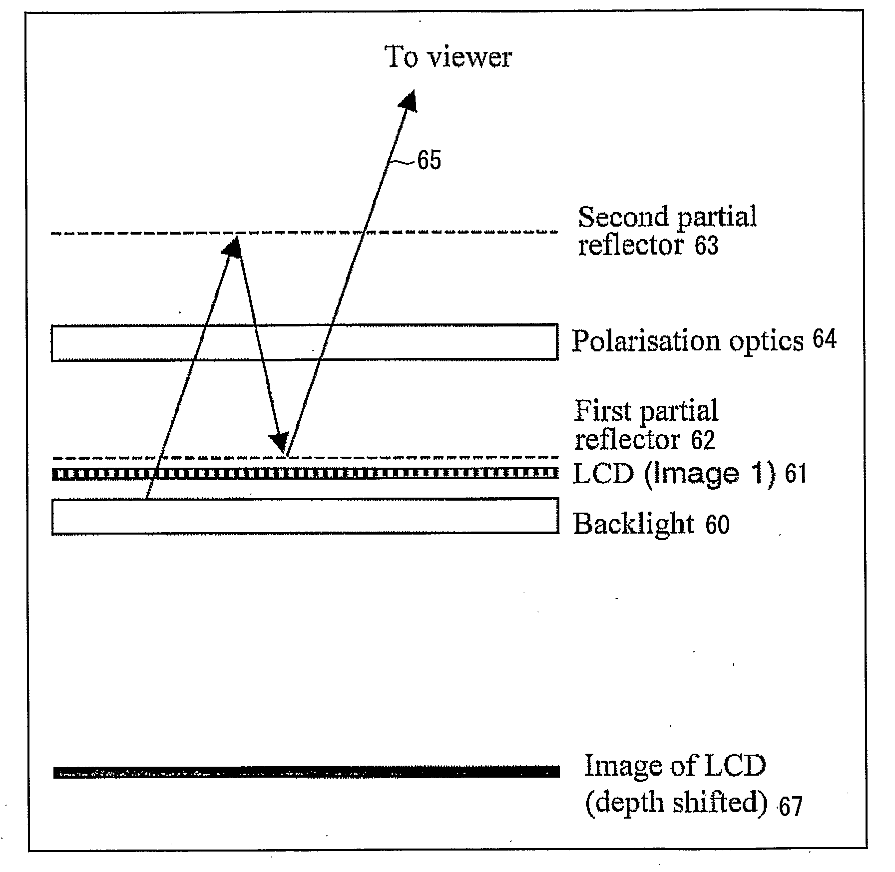
[0108]FIGS. 8(a) and 8(b) illustrate the construction of a display and two operational modes of the display. The display comprises a backlight 60 disposed behind a spatial light modulator (SLM) in the form of a liquid crystal device (LCD) 61. First and second partial reflectors 62 and 63 are disposed in front of the LCD 61 (on the viewer side thereof) with polarization-modifying optics 64 disposed between the reflectors 62 and 63. The reflectors 62 and 63 are separated from each other by an appropriate spacing for producing a depth-shifted image and are parallel to each other and to an image surface of the LCD 61. For example, the partial reflectors 62 and 63 may be arranged to reflect one polarization state of light and to transmit the orthogonal state or may be partially reflecting mirrors (or combinations of reflecting elements) of some other type. The polarization optics 64 are arranged to change at least one polarization state of light passing in either or both directions throu...


PUM

PropertyMeasurementUnit
wavelengthsaaaaaaaaaa
angleaaaaaaaaaa
angleaaaaaaaaaa

Abstract

A multiple depth display provided for displaying images at different depths comprises a single display device (61), for displaying all of the images. An optical system (62, 63, 64) is disposed in front of the display device (61). The optical system comprises first and second spaced-apart partial reflectors (62, 63) and polarization optics (64) for providing first and second light paths for first and second images or sequences of images displayed by the device (61). The first light path (65) comprises partial transmission through the first reflector (62), partial reflection from the second reflector (63), partial reflection from the first reflector (62), and partial transmission through the second reflector (65) towards a viewing region.

Description

TECHNICAL FIELD[0001]The present invention relates to a display. Such a display may be used, for example, to provide an impression of depth or changed depth. Such a display may, for example, be used in information display applications including computer-aided design, games and television and in applications where warnings or other messages are required to stand out from a background. The present invention also relates to an instrument panel including such a display. The present invention further relates to an optical system and to an optical instrument including such a system.BACKGROUND ART[0002]It is known for vehicles, such as automobiles and aircraft, to include an electronic display providing an image of, for example, an instrument cluster for replacing discrete mechanical or electric dials. However, such displays generally provide limited realism because of their inability to produce images at different depths with respect to the display apparatus. In addition to limiting the r...

Claims


Application Information

Patent Timeline
Patent Type & Authority Applications(United States)
IPC IPC(8): G02F1/1335G02B27/14G02B27/28G02B27/22G02B30/25
CPCG02B27/2278H04N13/0488H04N13/042G02B30/52H04N13/322H04N13/388G02B30/00G02B30/25G02B30/40
Inventor EVANS, ALLANCURD, ALISTAIRWYNNE-POWELL, THOMASJACOBS, ADRIANSMITH, NATHANWALTON, EMMAGAY, GREGORY
Owner SHARP KK
Why Eureka
Try Eureka