RF Transceiver Adapted for Signal Isolators and Proximity Sensors

a transceiver and proximity sensor technology, applied in the direction of digital transmission, transmission, duplex signal operation, etc., can solve the problems of high amplification level, high power consumption of devices, and hazard to the receiving circuit or individuals in contact with the receiving circui

Inactive Publication Date: 2008-08-28
AVAGO TECH INT SALES PTE LTD
View PDF4 Cites 50 Cited by
  • Summary
  • Abstract
  • Description
  • Claims
  • Application Information

AI Technical Summary

Problems solved by technology

The fraction of the transmitted energy that reaches the receiver is usually quite small, and hence, such devices require a significant amount of power and high amplification levels at the receiver.
For example, the transmitting circuit could utilize high internal voltages that would present a hazard to the receiving circuit or individuals in contact with that circuit.
Optical transceivers are energy inefficient for two reasons.
First, the fraction of the electrical energy that is converted to light is relatively small.
Second, the fraction of the light energy that is converted back to electrical energy is also small.
That is, the energy efficiency of the device is small.
In addition, RF transceivers typically operate at frequencies that require relatively large antennae.
Hence, RF transceivers have not been able to compete with optical transceivers in consumer applications requiring small transceivers and limited power consumption.
The need for the separate antennae increases the cost of the transceiver, and hence, further limits the applications that can utilize RF transceivers.

Method used


Image

  • RF Transceiver Adapted for Signal Isolators and Proximity Sensors
  • RF Transceiver Adapted for Signal Isolators and Proximity Sensors
  • RF Transceiver Adapted for Signal Isolators and Proximity Sensors

Examples


Embodiment Construction

[0018]The present invention is based on the observation that at frequencies in 100 GHz range, a RF transceiver that operates in the near field can be constructed on a substrate that is small enough to be useful in many handheld devices and that has an electrical efficiency that exceeds that of optical transceivers.

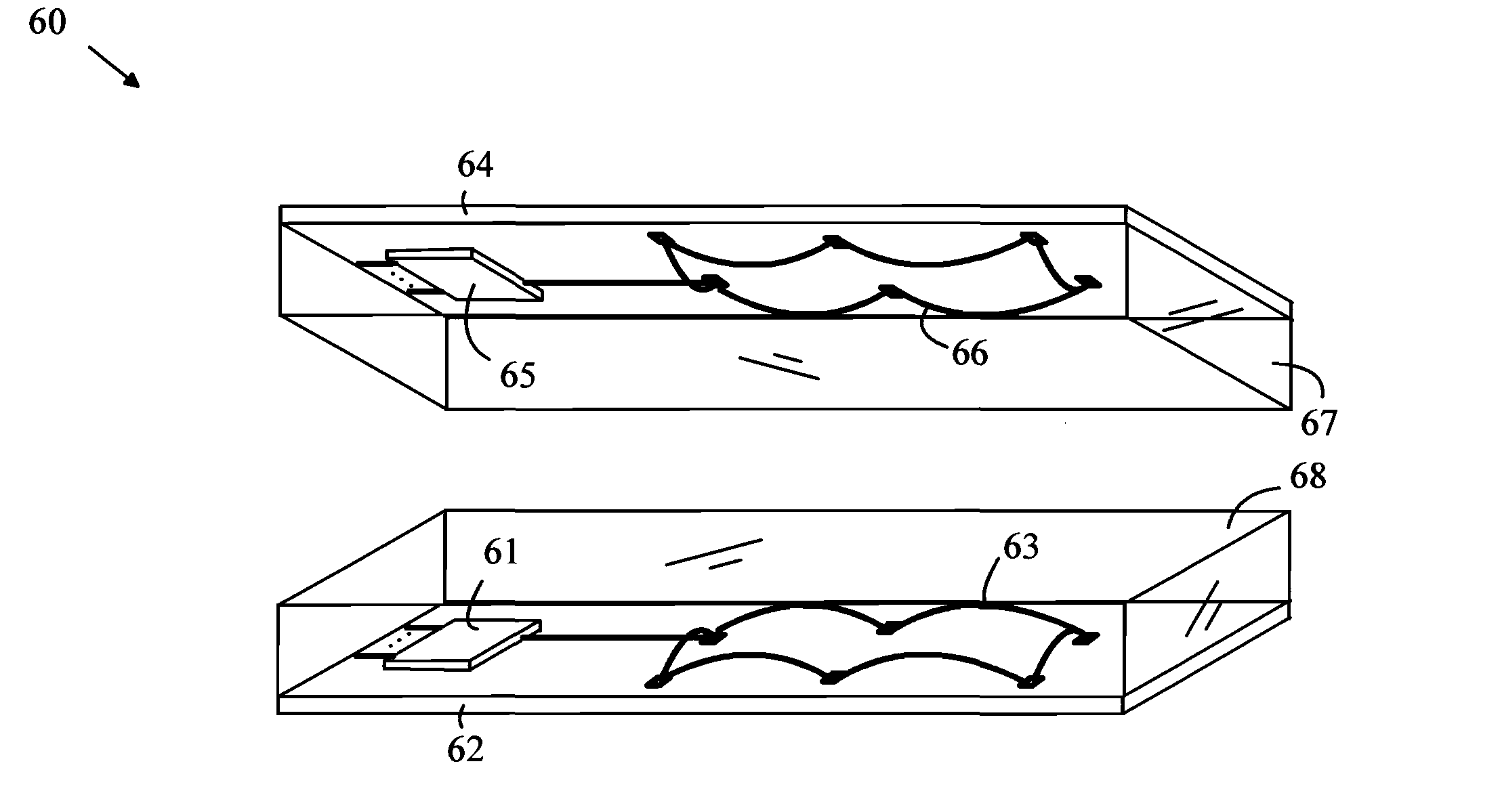
[0019]The manner in which the present invention provides its advantages can be more easily understood with reference to an RF transceiver that is configured to provide a galvanic isolator. A galvanic isolator can be viewed as a split circuit element in which the first portion of the circuit element is the transmitter and the second portion is the receiver of the transceiver. The two portions are disposed on a substrate and connected to separate power supplies having grounds and power rails that are not connected to one another in a manner that prevents interference in one portion of the isolator to propagate to the other portion of the isolator. In the case of an RF transc...


PUM


Abstract

A transceiver having a transmitting antenna, a receiving antenna, and a substrate having transmitter and receiver dies is disclosed. The transmitter generates an RF signal having a carrier frequency and the receiver detects and amplifies signals of the carrier frequency. The transmitting antenna and / or the receiving antenna includes a first wire antenna loop having a length greater than or equal to one tenth of a wavelength of the carrier frequency. The first wire antenna loop is connected to the transmitter die by a wire bond on a bond pad of the transmitter die. The antenna loop or loops can be encapsulated in an insulating material to protect the loops and fix the loops in space. The transceiver can be configured to operate as a galvanic isolator or a proximity detector.

Description

BACKGROUND OF THE INVENTION[0001]Transceivers are utilized in a number of systems to transmit and receive data and to implement proximity detectors and galvonic isolators. Transceivers utilize a transmitter to send data on a carrier and a receiver to detect the modulated carrier and extract data from that signal. Transceivers based on optical and RF carriers are known to the art.[0002]In a proximity detector, the signal from the transmitter is reflected from an object, and, when the object is within range, the reflected signal is detected by the receiver. The fraction of the transmitted energy that reaches the receiver is usually quite small, and hence, such devices require a significant amount of power and high amplification levels at the receiver.[0003]Galvonic isolators provide a means for moving logic signals between two circuits that must otherwise be electrically isolated from one another. For example, the transmitting circuit could utilize high internal voltages that would pr...

Claims


Application Information

Patent Timeline
Patent Type & Authority Applications(United States)
IPC IPC(8): H04B1/38H04B1/28
CPCH01Q7/00H01Q1/24H01L2224/4813H01L2924/19107
Inventor TROTT, GARY R.
Owner AVAGO TECH INT SALES PTE LTD
Why Eureka
Try Eureka