
Knee brace having a rigid frame and patellofemoral support

a rigid frame and knee brace technology, applied in the field of knee braces, can solve the problem that the knee brace is susceptible to modification, and achieve the effect of reducing the risk of fracture and fractur

Active Publication Date: 2008-08-28
DJ ORTHOPEDICS
View PDF17 Cites 35 Cited by
  • Summary
  • Abstract
  • Description
  • Claims
  • Application Information

AI Technical Summary

Benefits of technology

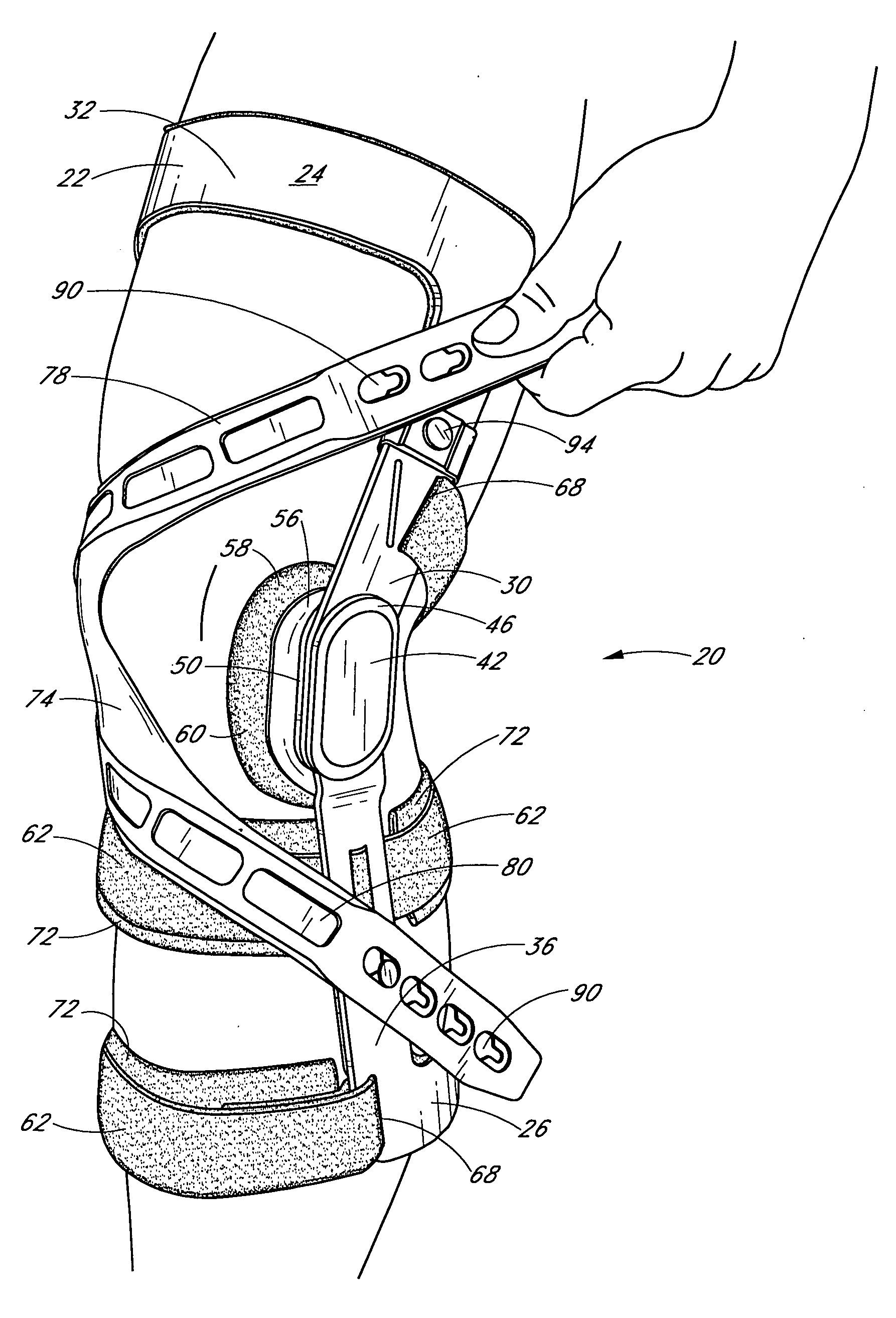
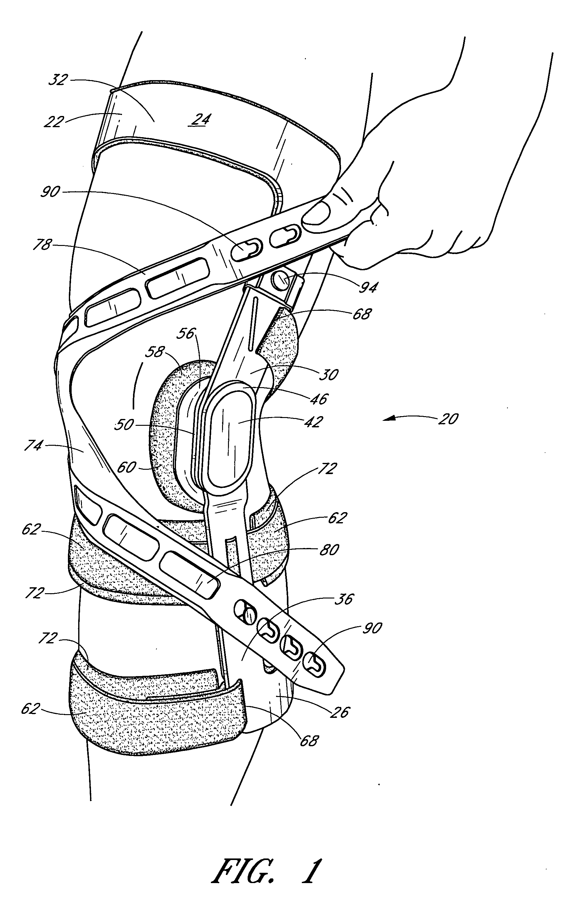
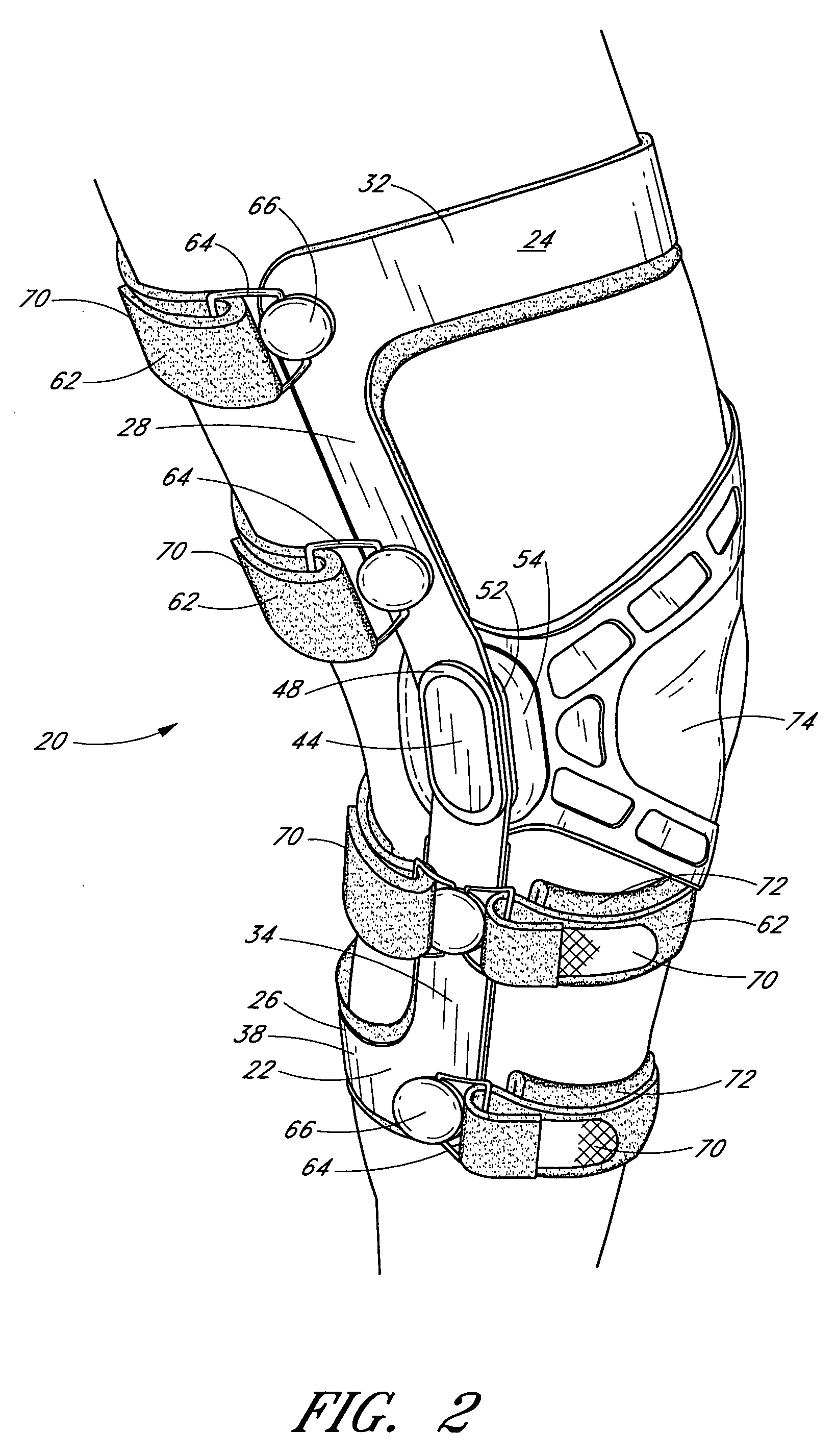
[0009]The preferred embodiments of the present knee brace having a rigid frame and patellofemoral support have several features, no single one of which is solely responsible for their desirable attributes. Without limiting the scope of this knee brace as expressed by the claims that follow, its more prominent features will now be discussed briefly. After considering this discussion, and particularly after reading the section entitled “Detailed Description of the Preferred Embodiments,” one will understand how the features of the preferred embodiments provide advantages, which include the combination of rigid brace components for providing ligament stability and / or providing relief from osteoarthritis pain and flexible brace components for providing patellofemoral support, support and symptomatic pain relief for patellofemoral dysfunction, including lateral patellar tracking errors, subluxation, dislocation, and patellar tendonitis, and ready conversion of a rigid brace frame into a brace that also provides patellofemoral support.

Problems solved by technology

This knee brace is, however, susceptible to modifications and alternate constructions from that discussed above that are fully equivalent.

Method used


Image

  • Knee brace having a rigid frame and patellofemoral support
  • Knee brace having a rigid frame and patellofemoral support
  • Knee brace having a rigid frame and patellofemoral support

Examples


Embodiment Construction

,” one will understand how the features of the preferred embodiments provide advantages, which include the combination of rigid brace components for providing ligament stability and / or providing relief from osteoarthritis pain and flexible brace components for providing patellofemoral support, support and symptomatic pain relief for patellofemoral dysfunction, including lateral patellar tracking errors, subluxation, dislocation, and patellar tendonitis, and ready conversion of a rigid brace frame into a brace that also provides patellofemoral support.

[0010]One embodiment of the present knee brace having a rigid frame and patellofemoral support comprises a knee brace for supporting and / or protecting a wearer's knee, while also providing support to the wearer's patella. The brace comprises a rigid brace frame including a rigid thigh cuff, a rigid calf cuff, and at least a first hinge pivotably securing the thigh cuff to the calf cuff. The brace further comprises a patellar strap havin...


PUM


Abstract

Embodiments of the knee brace disclosed herein provide a combination of external ligament support and / or relief from pain caused by osteoarthritis with patellofemoral support. The brace includes a rigid frame and a flexible strap configured to extend across the wearer's patella to provide anterior loading thereto. The strap is operatively secured at either end to components of the rigid frame, thereby providing maximum leverage for applying force to the wearer's patella. In some embodiments, the strap includes a removable and adjustable buttress for directly contacting the wearer's patella. The patellar strap provides dynamic loading to the patella through the wearer's range of motion for relief of patellofemoral dysfunction, such as patellar shift, subluxation and dislocation, and malalignments such as patella alta, patella baja, tilt and glide. In some embodiments, a conversion kit is provided for converting a rigid brace frame into a knee brace capable of providing patellofemoral support to a wearer's knee. The kit includes at least a patellar strap and at least one tab for securing the strap to the rigid frame.

Description

CROSS-REFERENCE TO RELATED APPLICATION[0001]This application claims priority to provisional application Ser. No. 60 / 722,739, filed on Sep. 30, 2005, the entire contents of which are hereby incorporated by reference.BACKGROUND OF THE INVENTION[0002]1. Field of the Invention[0003]The present invention relates generally to orthotic devices, and more specifically to knee braces for, for example, supporting ligament instability and / or treating patellofemoral dysfunction.[0004]2. Description of the Related Art[0005]Many orthotic devices support and / or protect the joints of the human anatomy, such as the knee joint. For instance, a wide variety of knee braces are generally intended to limit unnatural knee joint movement, which is a common source of structural damage to the knee. At the same time, such knee braces preferably allow a natural range of knee motion so as not to impede normal walking, running or other knee movements.[0006]Knee braces are also commonly used to prevent or remediat...

Claims


Application Information

Patent Timeline
Patent Type & Authority Applications(United States)
IPC IPC(8): A61F5/00
CPCA61F2005/0176A61F5/0123
Inventor KAZMIERCZAK, ANDYMARTIN, JOHNGILDERSLEEVE, RICHARD E.FULKERSON, JOHNJACOBSON, KURTSELIGMAN, SCOTT
Owner DJ ORTHOPEDICS
Learn More