Navigation system, enlarged intersection image displaying method used in the system, and map information generating method

a navigation system and intersection image technology, applied in navigation instruments, traffic control systems, navigation systems, etc., can solve problems such as insufficient display, complex calculations, and voice instruction that is not consistent with the driver's perception, and achieve the effect of enlarged intersections

Active Publication Date: 2008-08-28
ALPINE ELECTRONICS INC
View PDF15 Cites 38 Cited by
  • Summary
  • Abstract
  • Description
  • Claims
  • Application Information

AI Technical Summary

Benefits of technology

[0015]Accordingly, it is an object of the present invention to determine a traveling direction at an intersection in a simple manner and thereby correctly announce a traveling direction and / or display an enlarged intersection image.
[0018]It is yet another object of the present invention to correctly announce a traveling direction or display an enlarged intersection image even at two consecutive intersections.
[0029]Moreover, according to the present invention, if two intersections are consecutive, a direction connecting an approach link crossing point and the first intersection is set as an approach direction, and a direction connecting the first intersection and a second intersection is set as an exit direction. A traveling direction for the first intersection is determined based on the angular difference between the approach direction and the exit direction of the first intersection. Additionally, a coordinate position on the screen for the intersection is determined, thus allowing the navigation system to correctly announce the traveling direction to a user and display an enlarged intersection image such that the entire approach link is aligned with the 12 o'clock direction on the screen.
[0030]Additionally, according to the present invention, a traveling direction at the first intersection can be correctly estimated. Thus, if the traveling direction at the first intersection is a straight direction, a slight right turn direction, or a slight left turn direction, the first intersection can be displayed at the horizontal center of the screen. If the traveling direction is a right turn direction or a sharp right turn direction, the intersection can be displayed on the left side of the screen, as viewed in a horizontal direction. If the traveling direction is a left turn direction or a sharp left turn direction, the intersection can be displayed on the right side of the screen, as viewed in a horizontal direction. Therefore, according to the present invention, the area surrounding a road in the traveling direction can be presented to a user in more detail even if two intersections are consecutive.
[0031]In another aspect of the present invention, it is possible to adjust a coordinate position of the first intersection in a vertical direction to display both the first and second intersections on a screen.
[0032]Furthermore, according to an embodiment of the present invention, in the case where two intersections are consecutive (that is, the two intersections are located in close proximity to each other), a crossing point between a circle having a predetermined radius and its center set to a second intersection and a link exiting from the second intersection is determined, and a direction extending from the first intersection to the second intersection is set as an approach direction. A direction connecting the second intersection and the crossing point for the second circle is set as an exit direction. Then, a traveling direction at the second intersection is determined based on the angular difference between the approach direction and the exit direction for the second intersection. Thus, a traveling direction at the second intersection can be correctly announced.

Problems solved by technology

This display orientation causes the area around the link L2, which is actually desired, to be insufficiently displayed.
Additionally, although a driver feels that the traveling direction is a left turn direction, the traveling direction is erroneously announced as a slight left turn direction or a straight direction.
This causes a problem in that the intersection is displayed on the left side of the enlarged intersection display, as shown in FIG. 23B.
Further, the navigation system says “in about xxx miles, make a sharp left turn then right turn.” However, as shown in FIG. 24B, this voice instruction is not consistent with the driver's perception.
However, this conventional technique calculates angles at multiple sampling points in order to determine a link direction, which requires complex calculations.
Moreover, the conventional technique is not compatible with consecutive intersections.

Method used


Image

  • Navigation system, enlarged intersection image displaying method used in the system, and map information generating method
  • Navigation system, enlarged intersection image displaying method used in the system, and map information generating method
  • Navigation system, enlarged intersection image displaying method used in the system, and map information generating method

Examples


Embodiment Construction

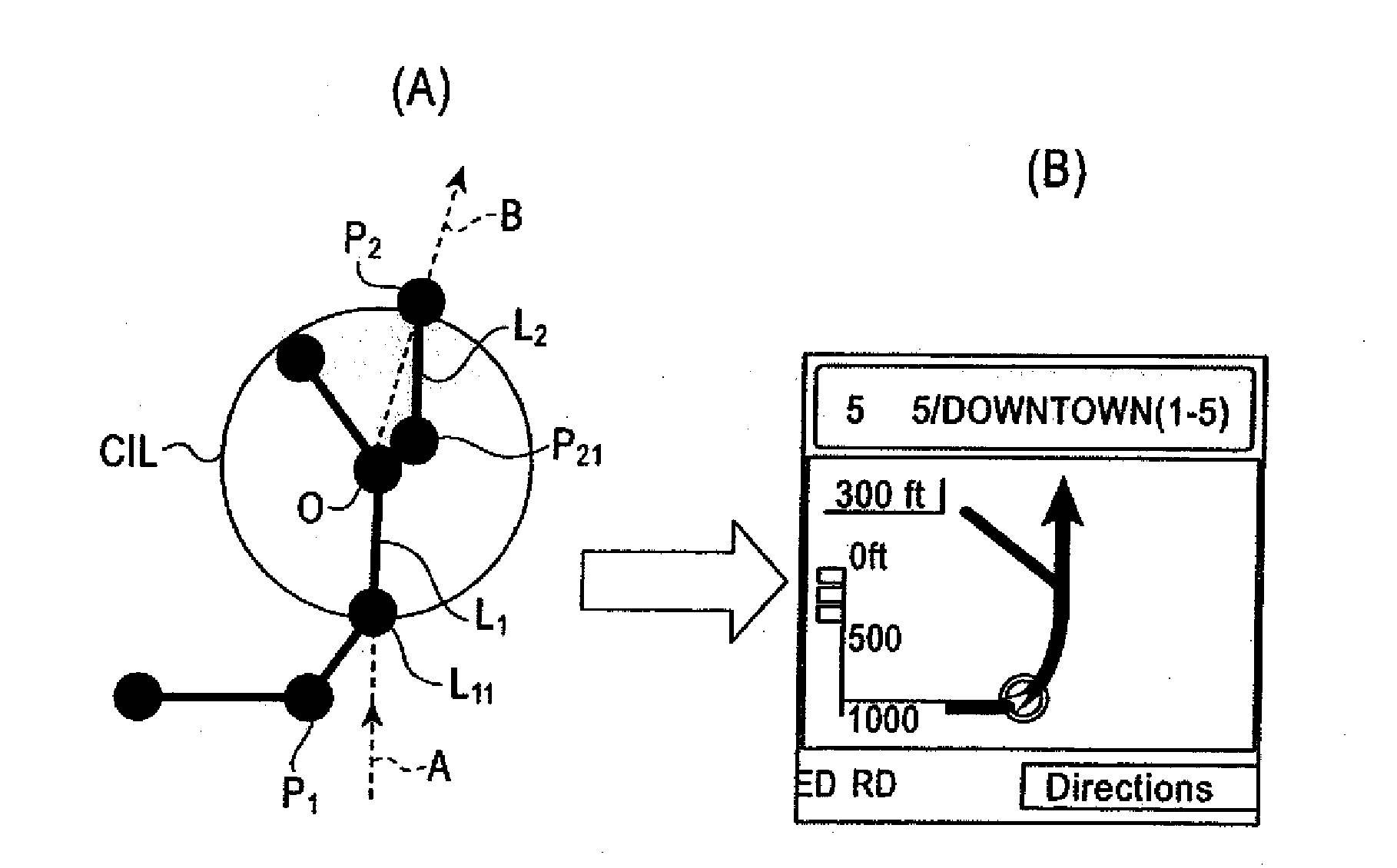
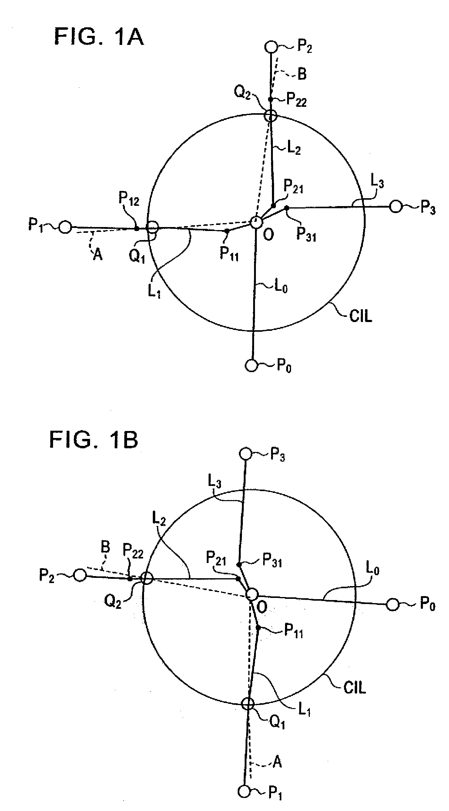
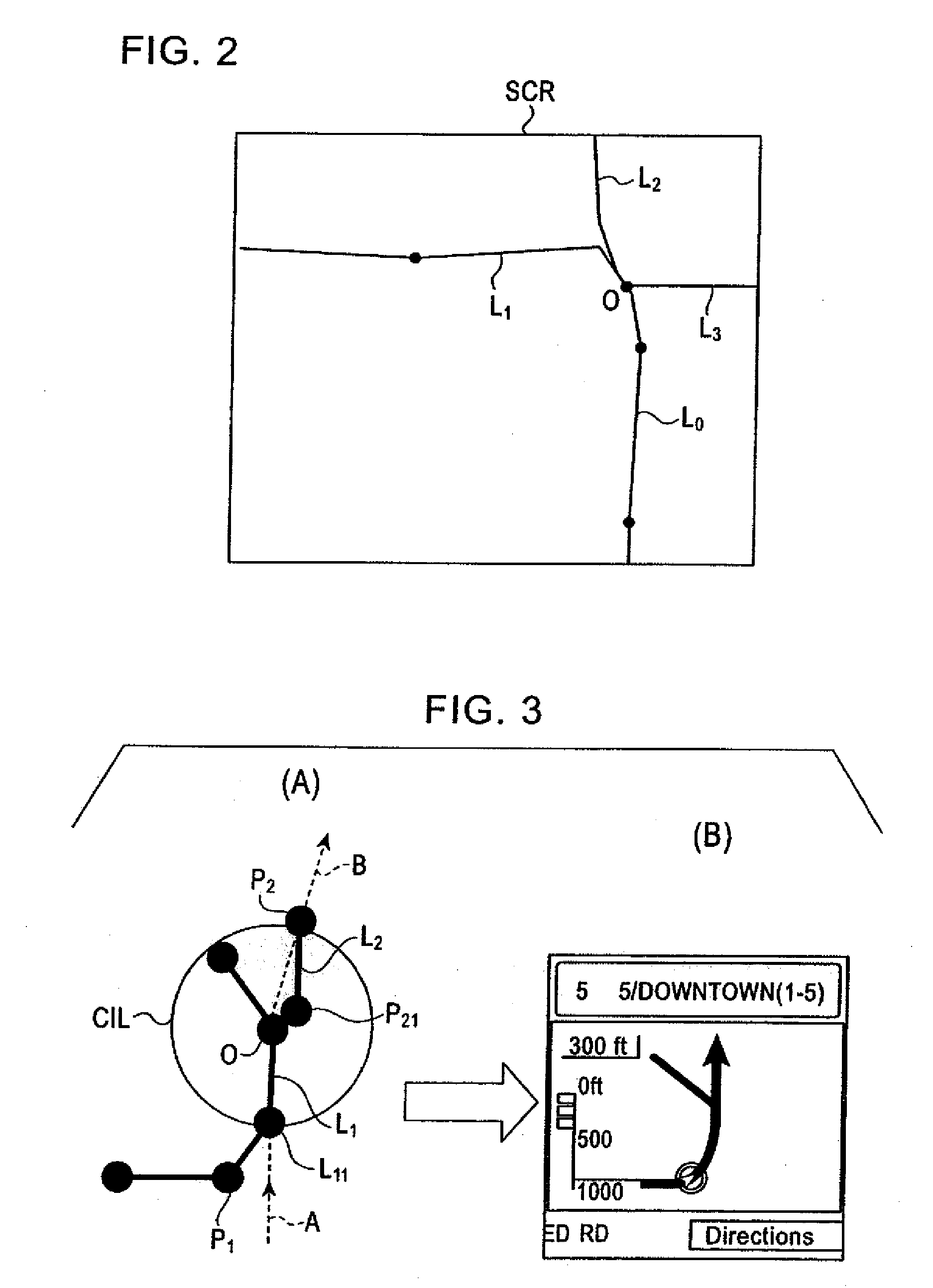
[0059]FIGS. 1A and 1B illustrate the principle of an enlarged intersection image displaying method according to an embodiment of the present invention. FIGS. 1A and 1B show links connected to an intersection. As shown in FIG. 1A, four links L0 to L3 including nodes P0 to P3 are connected to an intersection O, and shape complementary points P11, P21, and P31 are exits near the intersection O.

[0060]According to an embodiment of the present invention, an approach direction and an exit direction are determined as follows. Initially, the crossing points Q1 and Q2 between the approach link L1 and the exit link L2 and a circle CIL having a predetermined radius, for example 200 feet, with the circle's center set as the intersection O are calculated. A direction connecting the approach link crossing point Q1 and the intersection O is then set as an approach direction A, and a direction connecting the exit link crossing point Q2 and the intersection O is set as an exit direction B. When the e...


PUM


Abstract

When a vehicle travels along a guidance path and approaches an intersection, a vehicle navigation system determines crossing points between a circle having its center set to the intersection and a predetermined radius, and an approach link and an exit link for the intersection. The system also sets a direction connecting the crossing point for the approach link and the intersection as an approach direction, and sets a direction connecting the intersection and the crossing point for the exit link as an exit direction. The system determines a traveling direction at the intersection based on an angular difference between the approach direction and the exit direction, and determines a display position of the intersection on a screen. Further, an enlarged intersection image is drawn such that the approach direction is aligned with a 12 o'clock direction on the screen.

Description

BACKGROUND OF THE INVENTION[0001]The present application claims priority to Japanese Patent Application Number 2007-048843, filed Feb. 28, 2007, the entirety of which is hereby incorporated by reference.FIELD OF THE INVENTION[0002]The present invention relates to a navigation system, an enlarged intersection image display method used in the system, and a map information generating method. In particular, the present invention relates to a navigation system that displays an enlarged intersection image on a screen when a vehicle traveling along a guiding path reaches an intersection, and generates map information including voice information for informing a driver of a traveling direction at the intersection by voice.DESCRIPTION OF THE RELATED ART[0003]Conventional navigation systems detect a vehicle position and read map data at the vehicle position and its surroundings from a map recording medium (for example, a CD-ROM, a DVD disk, or a hard disk) in order to draw a map image on a dis...

Claims


Application Information

Patent Timeline
Patent Type & Authority Applications(United States)
IPC IPC(8): G01C21/34G06F17/00
CPCG01C21/3632
Inventor IWATANI, TATSUNORI
Owner ALPINE ELECTRONICS INC
Why Eureka
Try Eureka