Supercharge Your Innovation With Domain-Expert AI Agents!

Bridged extractor spring for firearms

a bridged extractor spring and firearm technology, applied in the field of extractor mechanism for firearms, can solve the problems of inability to reliably extract all cartridge cases, springs are too weak to reliably extract, and such high stress

Inactive Publication Date: 2008-09-04
WILSONS GUN SHOP
View PDF6 Cites 9 Cited by
  • Summary
  • Abstract
  • Description
  • Claims
  • Application Information

AI Technical Summary

Benefits of technology

[0006]A principal object of the invention is to provide the operator with a bolt and extractor assembly with a dramatically reduced rate of “failure to extract” malfunctions due to weak extractor springs. The “failure to extract” malfunction rate is directly related to the amount of force the extractor spring can apply to the extractor. The bridged extractor spring will provide sufficient extractor force at a reduced level of torsional stress with the result being a much longer service life.
[0015]A fourth unique improvement is that the usage rate of new bridged extractor springs will be much less than those of the current extractor spring due to its longer service life. That also means that the operator will not have to monitor his usage of the weapon and then change out his extractor spring to assure proper operation of his M4 / M16.

Problems solved by technology

This spring is exposed to such high stresses during operation that in a very small number of cycles the spring is too weak to reliably extract all expended cartridge cases from the chamber of the weapon.
This malfunction is known as a “failure to extract”.
Unfortunately the effective spring rate of the rubber material is sensitive to the environmental temperatures so that the total force applied to the extractor varies considerably with ambient temperature.
The rubber piece is also in intimate contact with the spring and grit from the environment can lodge into the rubber and act to abrade the spring wire as the weapon fires, thus prematurely weakening the spring.
The problem with both of these designs is that they require changing the complete bolt and barrel assemblies in the weapon in order to incorporate the alteration.
The bridged extractor spring will provide sufficient extractor force at a reduced level of torsional stress with the result being a much longer service life.

Method used


Image

  • Bridged extractor spring for firearms
  • Bridged extractor spring for firearms
  • Bridged extractor spring for firearms

Examples


Embodiment Construction

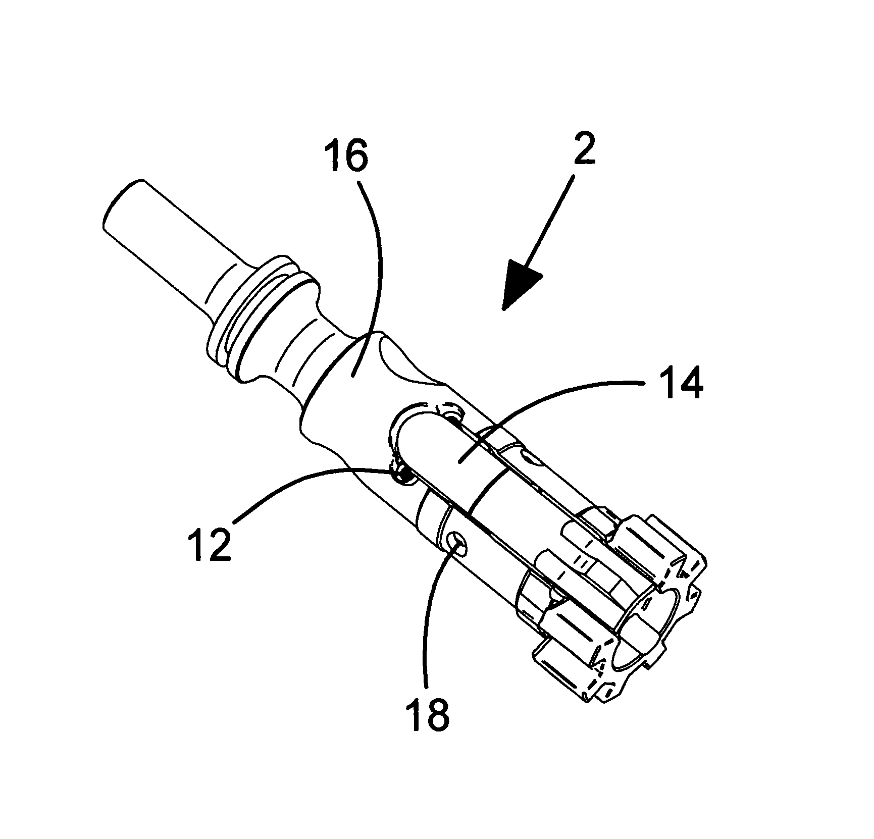
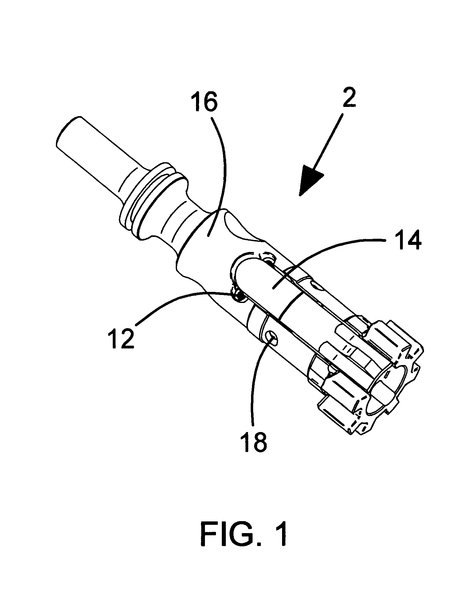
[0020]Referring in detail to FIG. 1 of the drawings, the bolt and extractor assembly 2, consists of a bolt body 16, a bridged extractor spring 12, an extractor 14 and an extractor pivot pin 18.

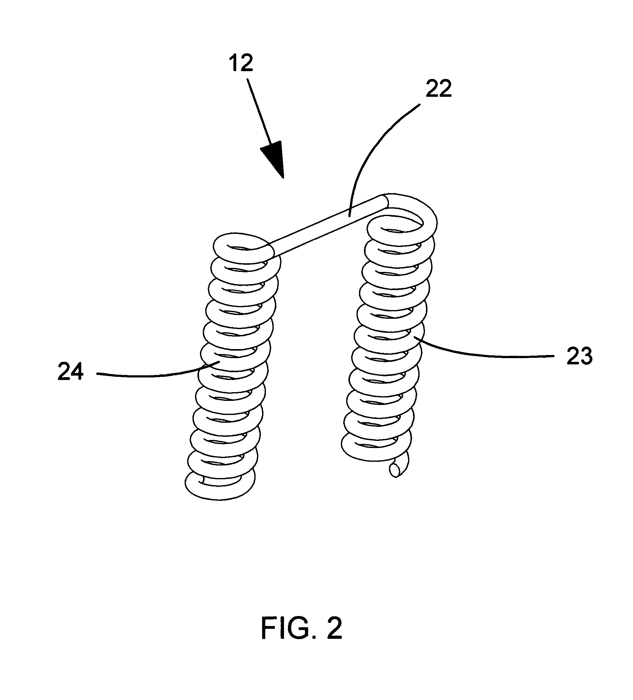
[0021]Referring to FIG. 2, the bridged extractor spring 12, consists of two helical wound spring coils 23 and 24 connected with bridging wire 22.

[0022]Referring to FIG. 3, the bolt body 16, has been modified by providing spring pockets 62 and 63 which straddle the bore for the firing pin 65. Clearance cut 64 provides the space for the bridging wire 22 to fit beneath the extractor 14 at its maximum angle relative to the bolt body (both not shown for clarity).

[0023]The bolt body 16 may be a standard M16 bolt that is re-configured to allow for installation of the bridged extractor spring 12 or it may be a newly manufactured M16 bolt that is pre-configured for installation of the bridged extractor spring 12. If the bolt body is a standard M16 bolt, the modifications to the bolt consist of machinin...


PUM


Abstract

New and unique improvements of prior known M4 / M16 firearms are disclosed that comprise (A) a bolt which, in addition to all of the normal M4 / M16 features is configured or reconfigured to accept a bridged extractor spring which straddles the firing pin and presses against the bottom of the extractor with the bridging wire, and (B) a bridged extractor spring which is a single part, wound with dual spaced helical coils connected with a bridge wire that maintains the spacing at the top of the spring. The bridge wire preferably crosses diagonally between and is tangent to both coils.

Description

BACKGROUND OF THE INVENTION[0001]1. Field of the Invention[0002]This application relates broadly to extractor mechanisms for firearms. More particularly, it concerns an improved form of extractor spring and the recess in the bolt that houses it for M4 / M16 and other military automatic and semi-automatic firearms.[0003]2. Description of the Prior Art[0004]The ubiquitous M4 / M16 firearms were designed with an extractor that is powered by a common helical compression spring that has one large loop that has an interference fit into a recess in the extractor. This spring sits well aft of the extractor pivot pin with the loose end of the sprint resting on a shelf above the firing pin. This spring is exposed to such high stresses during operation that in a very small number of cycles the spring is too weak to reliably extract all expended cartridge cases from the chamber of the weapon. This malfunction is known as a “failure to extract”. The short service life of the extractor spring has bee...

Claims


Application Information

Patent Timeline
Patent Type & Authority Applications(United States)
IPC IPC(8): F41A15/12
CPCF41A15/14
Inventor OLSON, DOUGLAS DEAN
Owner WILSONS GUN SHOP
Features
  • R&D
  • Intellectual Property
  • Life Sciences
  • Materials
  • Tech Scout
  • Unparalleled Data Quality
  • Higher Quality Content
  • 60% Fewer Hallucinations
Learn More