Ratchet wrench that is mounted closely

Inactive Publication Date: 2008-09-04
YU HSIANG CHEN
View PDF5 Cites 7 Cited by
  • Summary
  • Abstract
  • Description
  • Claims
  • Application Information

AI Technical Summary

Benefits of technology

[0005]The present invention is to mitigate and/or obvia

Problems solved by technology

However, the protrusion 15 of the drive block 14 is easily detached from the recess 13 of the control button 12, so that the control

Method used


Image

  • Ratchet wrench that is mounted closely
  • Ratchet wrench that is mounted closely
  • Ratchet wrench that is mounted closely

Examples


Example

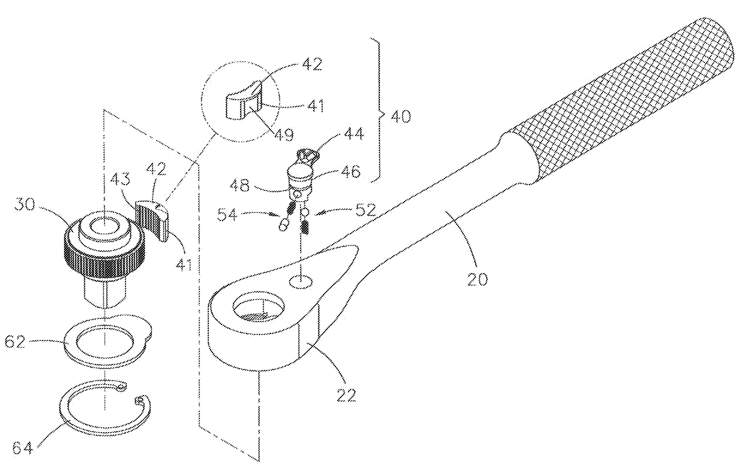
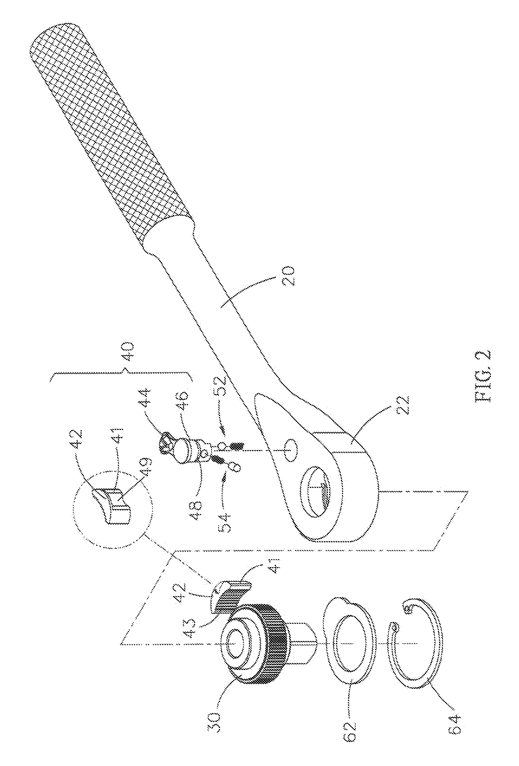
[0017]Referring to the drawings and initially to FIGS. 2 and 3, a ratchet wrench in accordance with the preferred embodiment of the present invention comprises a wrench body 20, a ratchet wheel 30 mounted on the wrench body 20, and a drive device 40 mounted on the wrench body 20.

[0018]The drive device 40 includes a pawl member 41 pivotally mounted in the wrench body 20 to mesh with the ratchet wheel 30 and formed with an outwardly protruding insert 42, a drive block 46 rotatably mounted on the wrench body 20 to control pivot movement of the pawl member 41 and having a periphery formed with a radially extending slot 48 facing the pawl member 41 to receive the insert 42 of the pawl member 41, and a control button 44 mounted on the drive block 46 to rotate the drive block 46.

[0019]The insert 42 of the pawl member 41 has a substantially arc-shaped profile and is directed toward a horizontal direction. The insert 42 of the pawl member 41 has a sheet shape. The drive block 46 has a column...


PUM


Abstract

A ratchet wrench includes a wrench body, a ratchet wheel, and a drive device. The drive device includes a pawl member, a drive block, and a control button. Thus, the insert of the pawl member is inserted into the slot of the drive block so that the pawl member and the drive block are combined integrally, and the pawl member is limited in the head portion of the wrench body, so that the pawl member and the drive block are retained by the head portion of the wrench body to prevent the drive block and the control button from being detached from the head portion of the wrench body by the push force of the first elastic unit.

Description

BACKGROUND OF THE INVENTION[0001]1. Field of the Invention[0002]The present invention relates to a ratchet wrench, and more particularly to a ratchet wrench whose operation direction is changeable.[0003]2. Description of the Related Art[0004]A conventional ratchet wrench in accordance with the prior art shown in FIG. 1 comprises a wrench body 10, a ratchet wheel 11 mounted on the wrench body 10, a pawl member 18 pivotally mounted in the wrench body 10 and having a first side formed with a plurality of teeth 17 meshing with a surface of the ratchet wheel 11, a drive block 14 rotatably mounted on the wrench body 10 to control pivot movement of the pawl member 17 and having a top formed with a protrusion 15, a control button 12 mounted on the drive block 14 to rotate the drive block 14 and having a bottom formed with a recess 13 mounted on the protrusion 15 of the drive block 14, and a spring 16 biased between a second side of the pawl member 18 and a side of the drive block 14. In ope...

Claims


Application Information

Patent Timeline
IPC IPC(8): B25B13/22
CPCB25B13/463
Inventor YU, HSIANG-CHEN
Owner YU HSIANG CHEN
Why Eureka
Try Eureka