Cerebrospinal Fluid Evaluation Systems

a technology of cerebral veins and evaluation systems, applied in the field of cerebral veins, can solve the problems of thermistor signal variations, apparatus/methods disclosed in the same, and failure to teach or suggest an apparatus/method for quantifying the flow of fluid through the shun

Inactive Publication Date: 2008-09-04
NEURO DIAGNOSTIC DEVICES
View PDF100 Cites 30 Cited by
  • Summary
  • Abstract
  • Description
  • Claims
  • Application Information

AI Technical Summary

Benefits of technology

[0032]A method for evaluating cerebrospinal fluid (CSF) flow rate or flow status in a CSF shunt applied to the body of a patient for transmitting the CSF between first and second locations of the body, comprising: applying a first temperature sensor (e.g., a fast response thermistor) at a first location external to the body in a vicinity of the CSF shunt and applying a second temperature sensor (e.g., a fast response thermistor) at a second location external to the body and under which the CSF shunt is located, the first location being upstream of the second location; applying a control temperature sensor (e.g., a fast response thermistor) at a third location under which the CSF shunt is not located but which is aligned with the second temperature sensor, wherein the control temperature sensor provides temperature correction signals representative of a temperature of the exterior of the body; applying a temperature source directly to the first temperature sensor; determining a flow rate or flow status of the CSF through the shunt to provide a determined CSF flow rate or flow status; and adjusting the determined CSF flow rate in accordance with the temperature correction signals to provide a CSF flow rate corrected in accordance with the background temperature.
[0033]An apparatus for evaluating c

Problems solved by technology

However, among other things, the apparatus and method disclosed therein fails to teach or suggest an apparatus/method for quantifying the flow of the fluid th

Method used


Image

  • Cerebrospinal Fluid Evaluation Systems
  • Cerebrospinal Fluid Evaluation Systems
  • Cerebrospinal Fluid Evaluation Systems

Examples


Embodiment Construction

[0070]The invention of the present application involve improvements over an invention of an earlier application, namely, application Ser. No. 10 / 770,754 (U.S. Patent Publication No. 2005 / 0204811 (Neff)), and as such the present application is a continuation-in-part of application Ser. No. 10 / 770,754. Therefore, before discussing the invention of the present application (FIGS. 7-21), Applicants will first discuss the invention of application Ser. No. 10 / 770,754 (FIGS. 3-6).

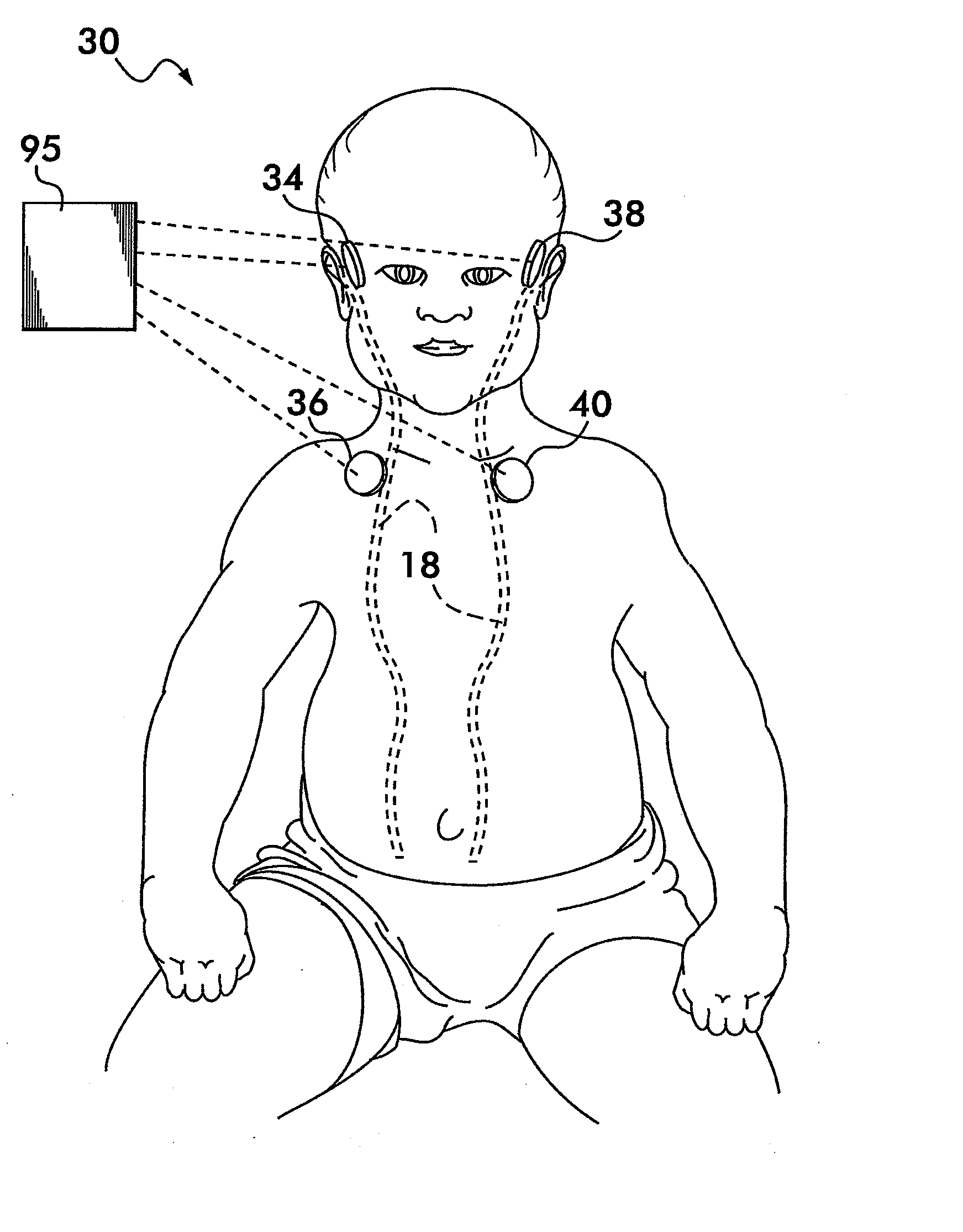
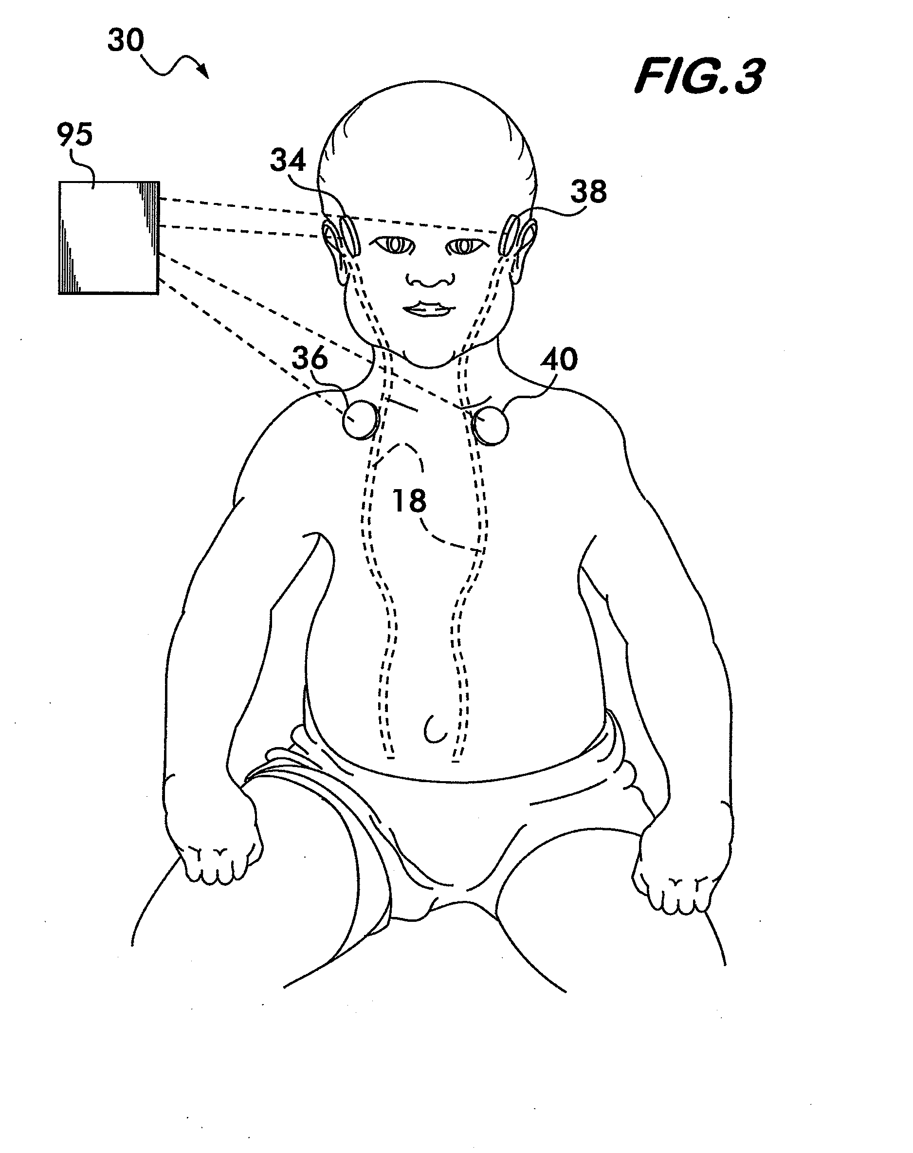
[0071]Referring now to FIG. 3, there is shown a CSF shunt evaluation system 30. The CSF shunt evaluation system 30 is provided with four sensors 34-40 disposed at predetermined locations on the body of the patient for determining the existence of CSF flow through the shunt tubing 18, and determining the flow and the flow rate of the CSF through the shunt tubing 18. Additionally, the placement of the four sensors 34-40 in the CSF shunt evaluation system 30 is adapted to permit the calculation of error signals due to...


PUM


Abstract

Methods and devices for testing for the presence, absence and/or rate of flow in a shunt tubing implanted under the skin by using a measurement pad having a plurality of temperature sensor configurations, or by using other temperature sensor arrangements, or by using a temperature sensitive material, which are positioned over, or in the vicinity of, the CSF shunt in substantially an upstream and downstream orientation. A temperature source, e.g., a cooling agent, is then applied at a predetermined location with respect to the measurement pad that is insulated from the temperature sensors, or to the temperature sensitive material. The movement of this temperature “pulse” is detected by the temperature sensors, or temperature sensitive material, via the shunt tubing as the CSF carries the temperature pulse while a control sensor detects the pulse via convection through the skin. The temperature data from these sensors are provided to a CSF analyzer that subtracts the control sensor data from each of the other sensors for determining a CSF shunt flow status or flow rate. A reader is used to optically or electrically detect the changes in the temperature sensitive material for determining a CSF shunt flow status or flow rate.

Description

CROSS-REFERENCE TO RELATED APPLICATIONS[0001]This application is a Continuation-in-Part application of, and claims the benefit under 35 U.S.C. §120 of, application Ser. No. 10 / 770,754 filed on Feb. 3, 2004 entitled CEREBRAL SPINAL FLUID SHUNT EVALUATION SYSTEM, and whose entire disclosure is incorporated by reference herein. Furthermore, this utility application also claims the benefit under 35 U.S.C. §119(e) of Provisional Application Ser. Nos. 60 / 911,687 filed on Apr. 13, 2007, entitled CEREBROVASCULAR FLUID EVALUATION SYSTEM HAVING THERMAL FLOW AND FLOW RATE MEASUREMENT PAD; 60 / 939,205 filed on May 21, 2007, entitled A METHOD AND DEVICE FOR MEASURING FLOW IN TUBES IMPLANTED SUBSCUTANEOUSLY; 60 / 941,827 filed on Jun. 4, 2007, entitled A METHOD AND DEVICE FOR DETECTING FLOW IN SUBCUTANEOUSLY-IMPLANTED SHUNTS / TUBING USING A TEMPERATURE SOURCE DIRECTLY OVER A TEMPERATURE SENSOR; and 60 / 989,284 filed on Nov. 20, 2007 entitled CSF EVALUATION SYSTEM USING FAST RESPONSE TEMPERATURE SENSOR...

Claims


Application Information

Patent Timeline
IPC IPC(8): A61B5/01A61M27/00
CPCA61B5/01A61M2205/3379A61M27/006A61B5/031
Inventor FRITZ, FREDERICK J.SWOBODA, MAREK
Owner NEURO DIAGNOSTIC DEVICES
Why Eureka
Try Eureka