Gas-Cooled Plasma Arc Cutting Torch

a plasma arc and cutting torch technology, applied in plasma welding apparatus, manufacturing tools, welding apparatus, etc., can solve the problems of increasing the associated equipment cost, increasing the cooling capacity, and requiring more maintenance, so as to prevent the swirling motion

Active Publication Date: 2008-09-11
HYPERTHERM INC
View PDF23 Cites 110 Cited by
  • Summary
  • Abstract
  • Description
  • Claims
  • Application Information

AI Technical Summary

Benefits of technology

[0019]In some embodiments, the shield also includes a central longitudinal axis. An interior surface of the shield can define in part a shield gas flow passage. In some embodiments, the shield includes a bleed port off-set from a central longitudinal axis of the shield that creates an exit flow counter to a swirling motion of the shield gas flow, thereby dampening the swirling motion of the shield gas flow exiting the exit orifice of the shield.

Problems solved by technology

Cooling capacity has been a limitation of previous designs relating to plasma arc torches.
Unfortunately, most of these cooling methods can require cooling systems external to the torch (e.g., which can include water supplies, reservoirs, heat exchange equipment, supply pumps, etc.).
External cooling systems can increase the associated equipment expense, can require more maintenance, be vulnerable to spills, and in some cases, can require disposal of the cooling medium.
The issue of cooling the plasma arc torch is more acute for higher current systems, as higher current systems can generate more heat and have larger cooling demands.
However, as explained above, these systems all suffer from the cost and maintenance issues associated with such systems.

Method used


Image

  • Gas-Cooled Plasma Arc Cutting Torch
  • Gas-Cooled Plasma Arc Cutting Torch
  • Gas-Cooled Plasma Arc Cutting Torch

Examples


Embodiment Construction

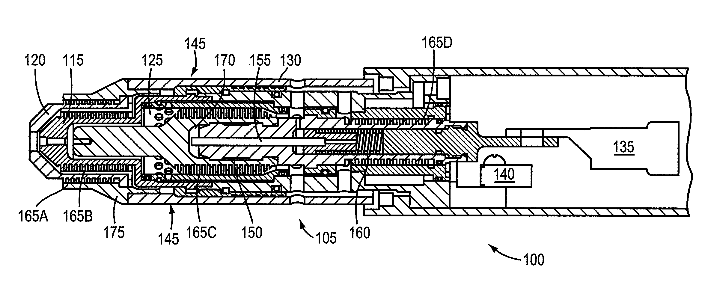
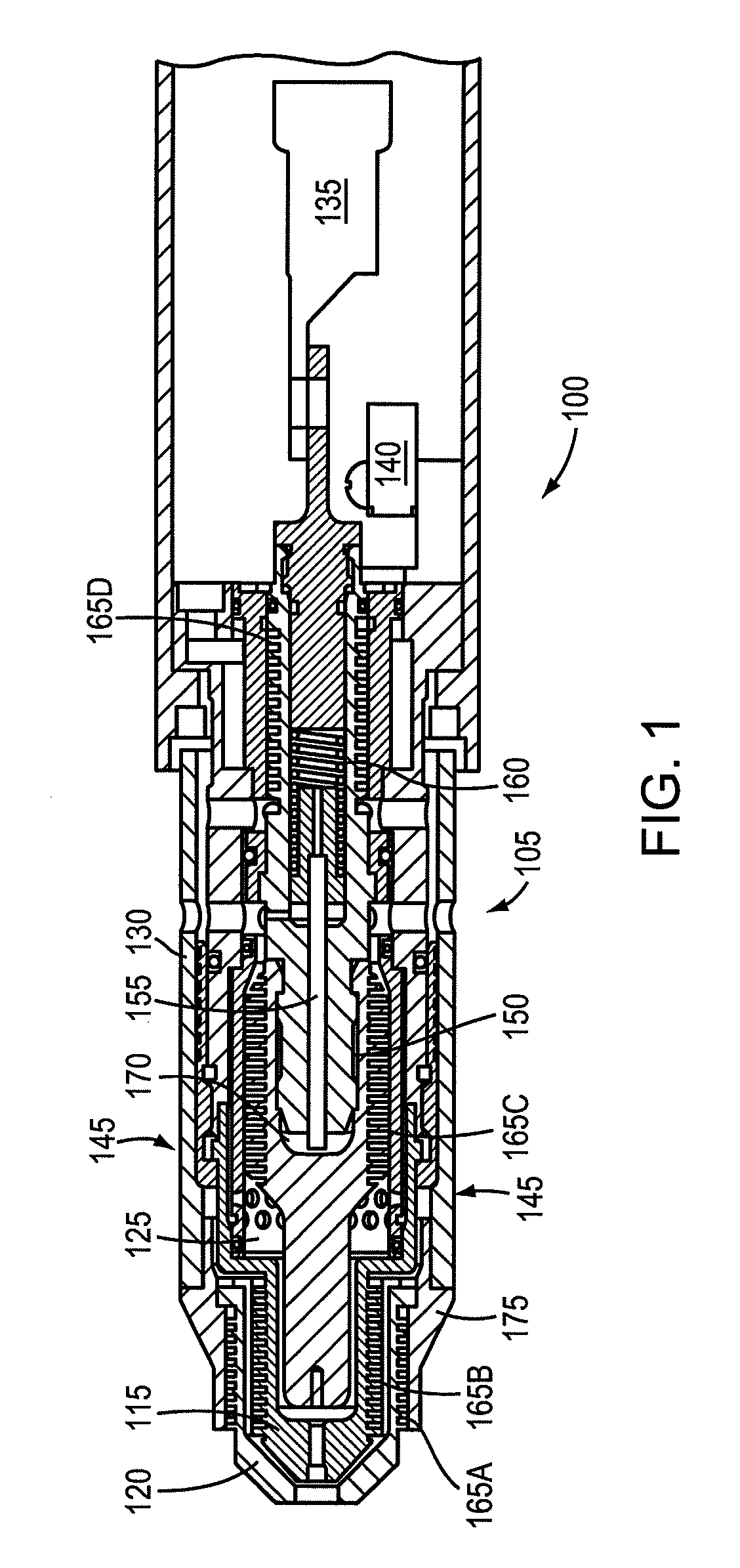
[0060]FIG. 1 is a cut-away view of a plasma arc torch. The plasma arc torch 100 can include components such as a torch body 105, electrode 110, nozzle 115, shield 120, swirl ring 125 and a retainer cap 130. The torch body 105 can include a plasma gas flow path for directing a plasma gas to a plasma chamber in which a plasma arc is formed. The electrode 110 can be disposed relative to a proximal end of the torch body 105. The nozzle 115 can be disposed relative to the electrode 110 at a distal end of the torch body 105, defining the plasma chamber. The shield 120 can be disposed relative to the nozzle 115 at the distal end of the torch body 105. The plasma arc torch can include a ring terminal 135 and cap sensor switch 140.

[0061]In some embodiments, the maximum diameter of the torch head 145 is less than about 1.2 inches. In some embodiments, the torch includes a semi-transparent torch sleeve. The cap-on sensor switch 140 can be a safety feature indicating whether a retaining cap 130...


PUM

PropertyMeasurementUnit
diameteraaaaaaaaaa
diameteraaaaaaaaaa
diameteraaaaaaaaaa

Abstract

A method and apparatus for a gas-cooled plasma arc torch. Components of the torch can include an electrode, nozzle and a shield, each of which can be gas-cooled. The nozzle can be disposed relative to the electrode and can include a generally hollow conductive body and a cooling gas flow channel defined by at least one fin disposed about an exterior surface of the body, the body providing a thermal conductive path that transfers heat between the nozzle to the cooling gas flow channel during operation of the torch. The shield can be disposed relative to the nozzle and can include a generally hollow conductive body and a cooling gas flow channel defined by at least one fin disposed about an exterior surface of the body, the body providing a thermal conductive path that transfers heat between the shield to the cooling gas flow channel during operation of the torch.

Description

CROSS-REFERENCE TO RELATED APPLICATION[0001]This application claims the benefit of and priority to U.S. provisional patent application Ser. No. 60 / 901,804 filed on Feb. 16, 2007, the disclosure of which is incorporated herein by reference in its entirety.FIELD OF THE INVENTION[0002]The invention relates generally to the cutting of materials and plasma arc torches. More specifically, the invention relates to design and cooling techniques to enhance the performance and life expectancy of plasma arc torches and torch consumables.BACKGROUND OF THE INVENTION[0003]Contact start plasma arc torches generally do not require the torch to contact the metal workpiece being cut or welded by the torch at the time the plasma arc is initiated. Contact start plasma torches can include “blow back” cutting torch technologies, which are described in U.S. Pat. No. 4,791,268 and U.S. Pat. No. 4,902,871, the contents of which are incorporated herein by reference in their entirety. The contact start plasma...

Claims


Application Information

Patent Timeline
Patent Type & Authority Applications(United States)
IPC IPC(8): B23K10/00
CPCH05H1/28H05H2001/3489H05H2001/3478H05H1/34H05H1/3478H05H1/3489
Inventor SANDERS, NICHOLAS A.
Owner HYPERTHERM INC
Why Eureka
Try Eureka