Light Emitting Device with Light Emitting Cells Arrayed

a light emitting device and light emitting cell technology, applied in the direction of electroluminescent light sources, electric lighting sources, semiconductor lamp usage, etc., can solve the problems of low light emitting efficiency per unit area, damage to conventional light emitting devices, and inoperable operation, so as to enhance the luminance and reliability of light emitting devices, the effect of improving the reliability of operation and luminan

Active Publication Date: 2008-09-11
SEOUL VIOSYS CO LTD
View PDF4 Cites 76 Cited by
  • Summary
  • Abstract
  • Description
  • Claims
  • Application Information

AI Technical Summary

Benefits of technology

[0014]According to the present invention, when manufacturing an AC light emitting device, the reliability of operation and the luminance of the AC light emitting device can be enhanced by controlling the size and number of diodes provided in a bridge rectifying circuit. Further, the luminance and the reliability of the light emitting device can be greatly enhanced by setting the size of diodes to be less than a certain size and controlling the number of diodes.

Problems solved by technology

Since only any one of the first and second light emitting cell blocks 1200a and 1200b is turned on in such a conventional reverse parallel light emitting device, there is a problem in that the light emitting efficiency per unit area is low.
When an excess voltage is particularly applied thereto, there is a problem in that the conventional light emitting device is damaged by the excess voltage and thus is not operated.

Method used


Image

  • Light Emitting Device with Light Emitting Cells Arrayed
  • Light Emitting Device with Light Emitting Cells Arrayed
  • Light Emitting Device with Light Emitting Cells Arrayed

Examples


Embodiment Construction

[0025]Hereinafter, a preferred embodiment of the present invention will be described in detail with reference to the accompanying drawings.

[0026]However, the present invention is not limited to the embodiment disclosed below but may be implemented into different forms. The present embodiment is provided only for illustrative purposes and for full understanding of the scope of the present invention by those skilled in the art. Throughout the drawings, like elements are designated by like reference numerals.

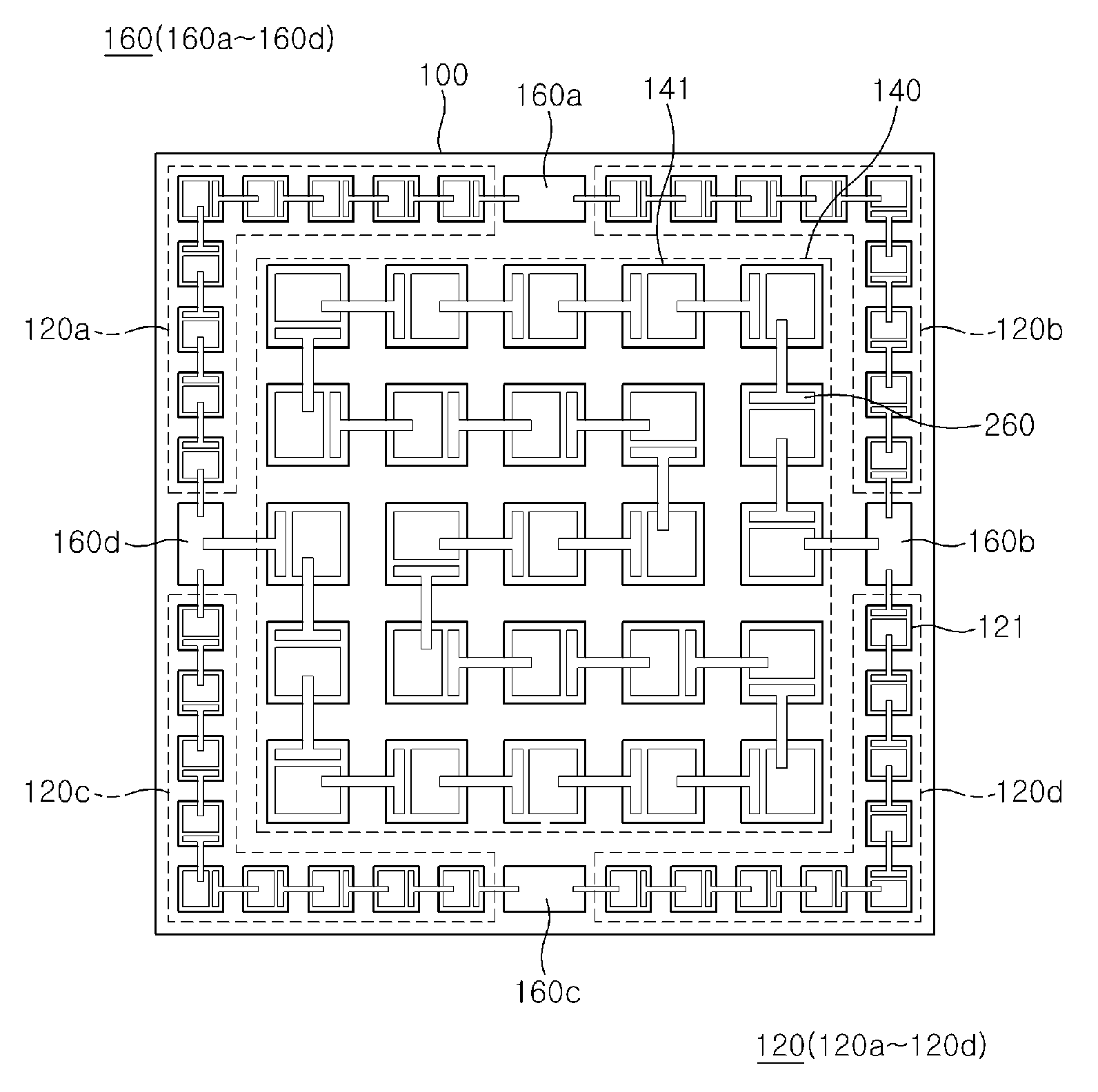
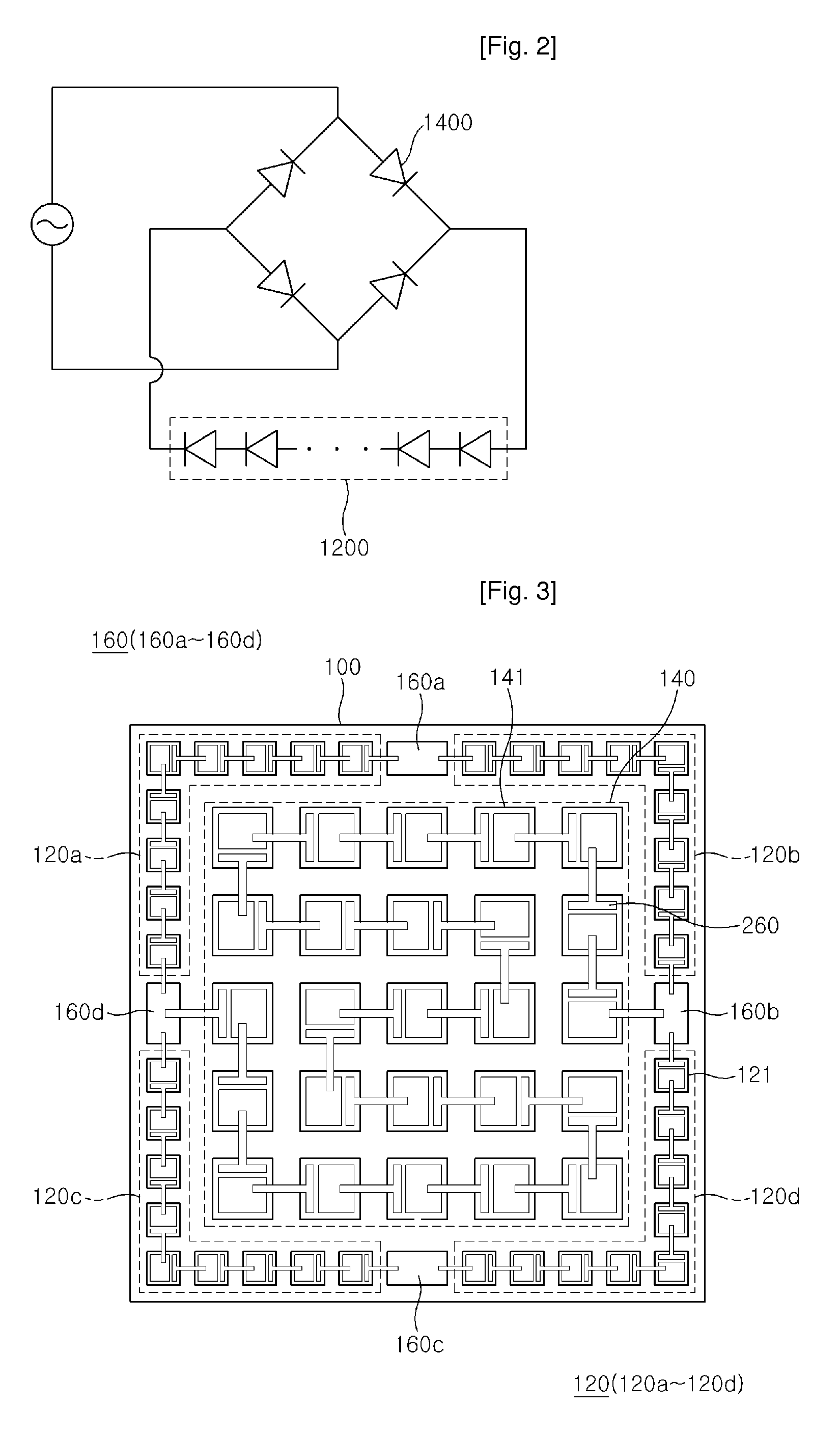
[0027]FIG. 3 is a plan view of a light emitting device according to the present invention, and FIG. 4 is an equivalent circuit diagram of FIG. 3.

[0028]As shown in FIG. 3, the light emitting device according to the present invention comprises a substrate 100, a light emitting cell block 140, a bridge rectifying circuit 120 and wires 260. The light emitting cell block 140 is provided on the substrate 100 and comprises a plurality of light emitting cells 141 connected in series. The b...


PUM


Abstract

The present invention relates to a light emitting device. The light emitting device according to the present invention comprises a light emitting cell block having a plurality of light emitting cells; and a bridge rectifying circuit connected to input and output terminals of the light emitting cell block, wherein the bridge rectifying circuit includes a plurality of diodes between nodes. In manufacturing an AC light emitting device with a bridge rectifying circuit built therein, the present invention can provide a light emitting device capable of enhancing the reliability and luminance of the light emitting device by setting the size of diodes of the bridge rectifying circuit to be a certain size and controlling the number thereof.

Description

TECHNICAL FIELD[0001]The present invention relates to an AC light emitting device, and more particularly, to an AC light emitting device with a bridge rectifying circuit formed therein.BACKGROUND ART[0002]As shown in FIG. 1, a conventional AC light emitting device comprises first and second light emitting cell blocks 1200a and 1200b, each of which has a plurality of light emitting cells connected in series on a substrate 1000. The first and second light emitting cell blocks 1200a and 1200b are arrayed in two lines from both electrodes 1600a and 1600b in different directions, i.e., connected in reverse parallel. As shown in FIG. 2, another conventional AC light emitting device comprises a bridge rectifying circuit having a light emitting cell block 1200 and four diodes 1400.[0003]The conventional reverse parallel light emitting device as shown in FIG. 1 does not comprise a rectifying circuit. When an AC voltage is applied to the light emitting device, the first and second light emitt...

Claims


Application Information

Patent Timeline
Patent Type & Authority Applications(United States)
IPC IPC(8): H05B37/02H01L33/00H01L33/08H01L33/32H05B44/00
CPCH01L27/15H05B33/0803Y02B20/348H05B33/0821H05B33/0809H01L2924/12041H01L2224/40137H01L24/40H01L27/156H01L33/62H01L2924/00014H01L2224/371H01L24/37H05B45/40H05B45/37H05B45/00Y02B20/30H01L2924/00H01L2224/37099H01L2224/84H01L24/36
Inventor LEE, JAE HOYOON, YEO JINHWANG, EU JINYVES, LACROIX
Owner SEOUL VIOSYS CO LTD
Why Eureka
Try Eureka