Method for producing radiation image conversion panel

Inactive Publication Date: 2006-03-09
KONICA MINOLTA MEDICAL & GRAPHICS INC
View PDF15 Cites 13 Cited by
  • Summary
  • Abstract
  • Description
  • Claims
  • Application Information

AI Technical Summary

Benefits of technology

[0010] An object of the present invention is to provide a method for producing a radiation image conversion panel which is remarkably improved in luminance of emitting light and in sharpness of an image, and to provide the radiation image conversion panel.

Problems solved by technology

However, the emitting amount of the light is not fully increased only by conducting a heat treatment and it may be possible that the clarity of the image is not fully enough or the luminance of the phosphor may be lowered by humidity.

Method used


Image

  • Method for producing radiation image conversion panel
  • Method for producing radiation image conversion panel
  • Method for producing radiation image conversion panel

Examples


example 1

[0118] Plural samples of the radiation image conversion panel were prepared and the luminance and the sharpness of the samples were evaluated.

[0119] (1) Preparation of Samples 1-1 Through 1-7

[0120] Seven square-shaped aluminum plates of 20 cm×20 cm each having a thickness of 500 μm were prepared for the substrate, and a light reflection layer was formed on one side of each of the plates. The light reflection was formed by depositing titanium oxide, manufactured by Furuuchi Kagaku Co., Ltd., and zirconium oxide, manufactured by Furuuchi Kagaku Co., Ltd., on the substrate by a known vapor deposition apparatus.

[0121] Next, a stimulable phosphor composed of CsBr:Eu was deposited on the light reflection layer of each of the substrates to form a stimulable phosphor layer. In concrete, a substrate was fixed in a vacuum chamber of the vapor deposition apparatus so that the surface of each of the substrate on which the light reflection layer was formed was faced to the vapor source and th...

example 2

(1) Preparation of Samples

[0136] Thirteen square-shaped aluminum plates of 20 cm×20 cm each having a thickness of 500 μm were prepares for the substrate, and a light reflection layer was formed on one side of each of the plates. The light reflection was formed by depositing titanium oxide, manufactured by Furuuchi Kagaku Co., Ltd., and zirconium oxide, manufactured by Furuuchi Kagaku Co., Ltd., on the substrate by a known vapor deposition apparatus.

[0137] Next, a stimulable phosphor composed of CsBr:Eu was deposited on the light reflection layer of each of the substrates to form a stimulable phosphor layer. In concrete, the substrates was fixed in a vacuum chamber of the vapor deposition apparatus so the surface of each of the substrate on which the light reflection layer was formed was faced to the vapor source and the temperature in the vacuum chamber was raised by 240° C. In such the situation, nitrogen gas was introduced into the vacuum chamber so that the vacuum degree in th...


PUM


Abstract

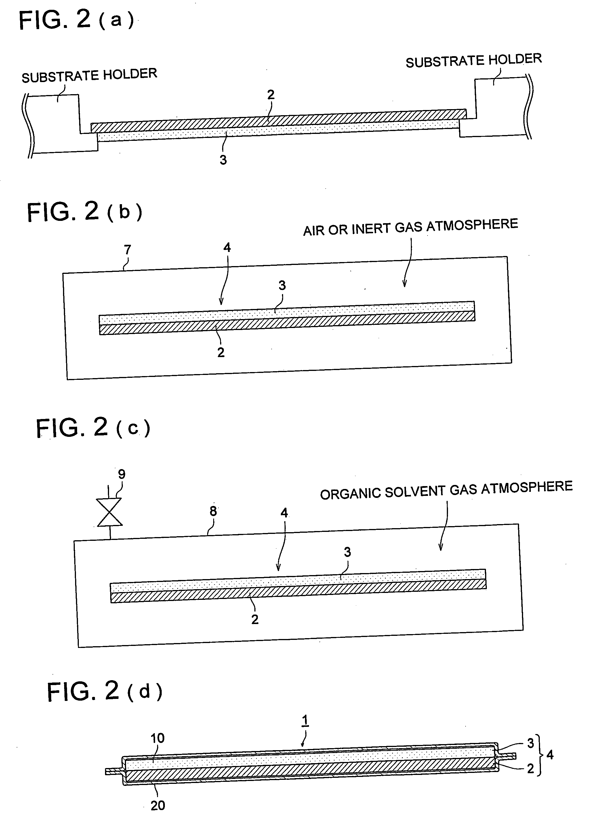
A method for manufacturing a radiation image conversion panel comprising the steps of: forming a stimulable phosphor layer on a substrate by a vapor deposition method to prepare a phosphor plate; heating the phosphor plate in an organic solvent gas; and sealing the phosphor plate with a moisture-proof protective film to prepare the radiation image conversion panel.

Description

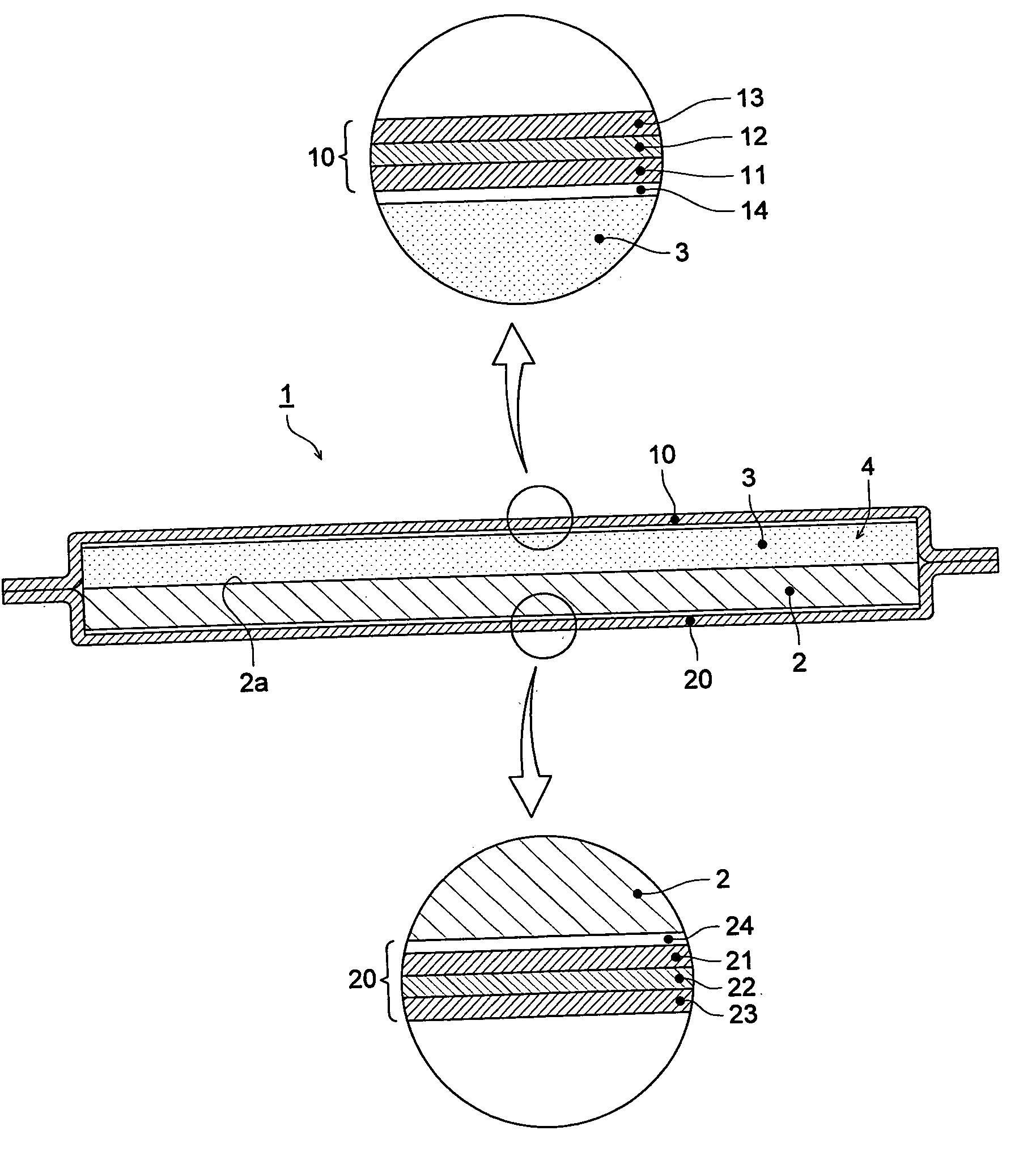
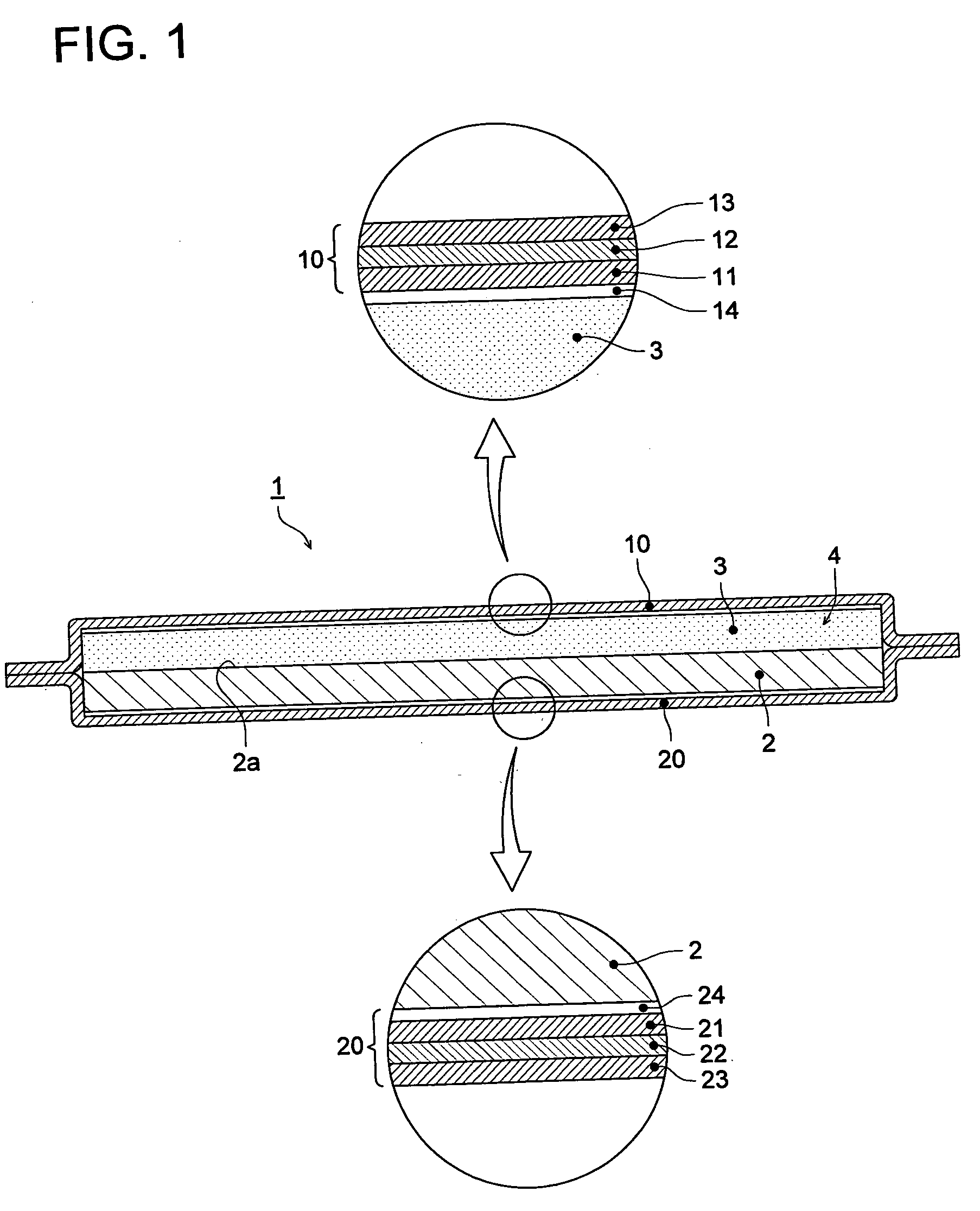
[0001] This application is based on Japanese Patent Application No 2004-262363 filed on Sep. 9, 2004, and No. 2004-266876 filed on Sep. 14, 2004 in Japanese Patent Office, the entire content of which is hereby incorporated by reference. FIELD OF THE INVENTION [0002] The present invention relates to a method for producing a radiation image conversion panel to be used for forming a radiation image of a subject and to a radiation image conversion panel. BACKGROUND [0003] A radiation image such as an X-ray image has been widely applied in the medical field for diagnosing a disease. Specifically, a radiation image obtained in combination of an intensifying paper and a film has been improved to achieve a high sensitivity and a high image quality during a long period of history and as the result, it is still now being used in the medical field of the world as an imaging system having a high reliability and a high cost performance. Recently, a computed radiography (CR) employing a stimulabl...

Claims


Application Information

Patent Timeline
IPC IPC(8): G21K4/00
CPCG21K4/00C09K11/7733
Inventor SHOJI, TAKEHIKOMORIKAWA, OSAMUKUDO, SHINJI
Owner KONICA MINOLTA MEDICAL & GRAPHICS INC
Why Eureka
Try Eureka