Image forming apparatus and control method thereof

a technology of image forming apparatus and control method, which is applied in the direction of electrographic process apparatus, instruments, optics, etc., can solve the problems of large consumption of toner, limited achieving high image quality, and inability to achieve high image quality, so as to prolong the cycle of detecting image quality density and maintain the density of printed image stably

Inactive Publication Date: 2008-09-11
S PRINTING SOLUTION CO LTD
View PDF6 Cites 8 Cited by
  • Summary
  • Abstract
  • Description
  • Claims
  • Application Information

AI Technical Summary

Benefits of technology

[0013]The present general inventive concept provides an image forming apparatus and a control method thereof that is capable of extending a cycle of detecting density of image quality long and maintaining density of a printed image stably by adjusting a toner supply amount according to changed density of a patch image which is detected by a density sensor with a predetermined detecting cycle.

Problems solved by technology

As described above, the methods for adjusting the amount of toner supplied into the development unit based on the toner density detected by the toner density sensor, have limits in achieving high image quality.
Accordingly, if the test printing operation is performed frequently, printing efficiency is deteriorated, and a toner is needlessly consumed largely by the test printing.
If a cycle of performing the test printing operation is set too long for that reason, it is difficult to immediately cope with the change in image quality, and efficiency of controlling the density of image quality is deteriorated.
As a result, the density of the printed image becomes unstable.

Method used


Image

  • Image forming apparatus and control method thereof
  • Image forming apparatus and control method thereof
  • Image forming apparatus and control method thereof

Examples


Embodiment Construction

[0043]Reference will now be made in detail to exemplary embodiments of the present general inventive concept, examples of which are illustrated in the accompanying drawings, wherein like reference numerals refer to like elements throughout. The embodiments are described below to explain the present general inventive concept by referring to the figures.

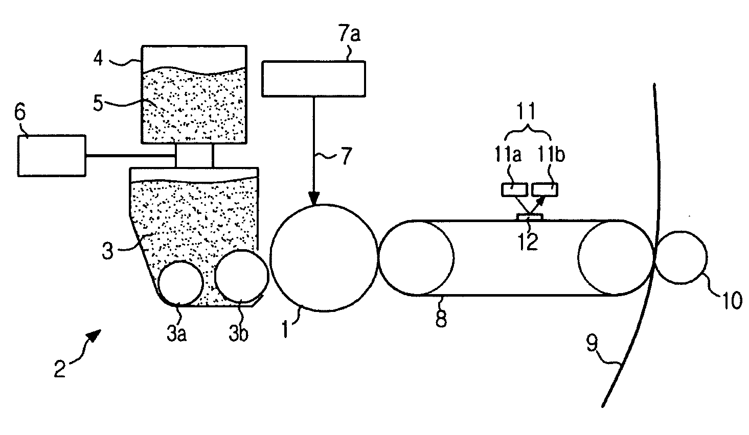
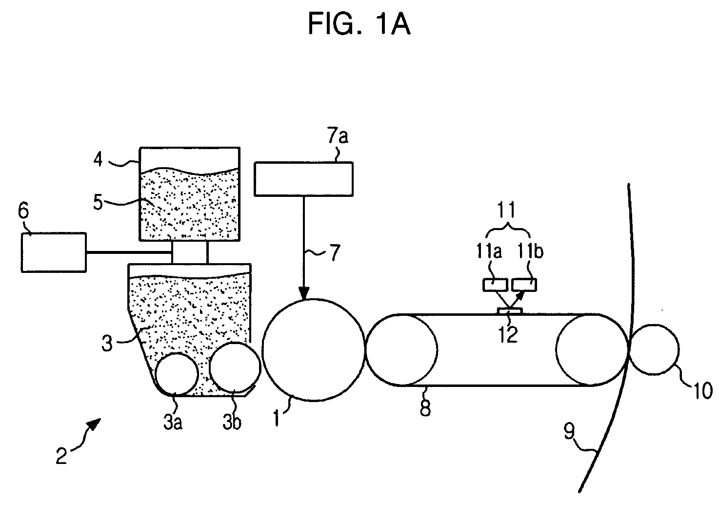
[0044]FIG. 1A is a view illustrating a printing process of an image forming apparatus according to an embodiment of the present general inventive concept.

[0045]The image forming apparatus according to the present embodiment includes a photosensitive drum 1, a development unit 2, an intermediate transfer belt 8, a printing medium, such as a transfer paper 9, and a transfer roller 10.

[0046]The development unit 2 includes a toner container 4, a toner supply motor 6, a supply roller 3a and a development roller 3b for performing the development using a developer 3. A toner 5 contained in the toner container 4 is supplied into a development ...


PUM


Abstract

An image forming apparatus and a control method thereof. The image forming apparatus includes an image input part, a development unit which is supplied with a toner and forms a developer to develop an input image inputted from the image input part, a transfer member to form a patch image, a density sensor which detects density of the patch image, and a toner supply amount control unit which sets a toner supply amount of the development unit according to changed density of the patch image which is detected by the density sensor with a predetermined detecting cycle and applies the set toner supply amount to operation of printing the input image. Accordingly, a cycle of test printing the patch image can be extended to a longer period, unnecessary consumption of the toner is prevented, and the density of the printed image can be maintained stably.

Description

CROSS-REFERENCE TO RELATED APPLICATIONS[0001]This application claims the benefit of Korean Patent Application No. 2007-0023523, filed on Mar. 9, 2007 in the Korean Intellectual Property Office, the disclosure of which is incorporated herein by reference in its entirety.BACKGROUND OF THE INVENTION[0002]1. Field of the Invention[0003]The present general inventive concept relates to an image forming apparatus, and more particularly, to an image forming apparatus and a control method thereof that adjusts a toner supply amount according to change in density of image quality of a patch image.[0004]2. Description of the Related Art[0005]An image forming apparatus includes a toner density sensor to control image density to apply a two-component developer. Examples of the image forming apparatus are disclosed in Japanese Patent Laid-Open Publication Nos. 2006-133535 and H11-272063.[0006]Japanese Patent Laid-Open Publication No. 2006-133535 discloses a toner density control method which contr...

Claims


Application Information

Patent Timeline
Patent Type & Authority Applications(United States)
IPC IPC(8): G03G15/10
CPCG03G2215/00059G03G15/0855G03G15/5058G03G15/0131G03G15/00G03G15/08
Inventor SHINICHI, HISATOMI
Owner S PRINTING SOLUTION CO LTD
Why Eureka
Try Eureka