Wave-power generation system

Inactive Publication Date: 2006-02-09
YIM MYUNG SHIK
View PDF55 Cites 46 Cited by
  • Summary
  • Abstract
  • Description
  • Claims
  • Application Information

AI Technical Summary

Benefits of technology

[0009] Therefore, an object of the present invention is to solve the problems involved in the prior art, and to provide a wave-power ge

Problems solved by technology

Since reserves of the petroleum and fossil fuel are limited, it should be exhausted with the passage of time.
For the atomic energy, a usable period of uranium is limited because of finite exhaustion thereof and serious issue of radioactive waste.
However, it is difficult to search the optimum position of the wind since a wind direction is different depending upon a season and position.
For the solar energy, there is a disadvantage in that since the percentage of sunshine is limited, a large-scale apparatus and an efficient energy transforming te

Method used


Image

  • Wave-power generation system
  • Wave-power generation system
  • Wave-power generation system

Examples


first embodiment

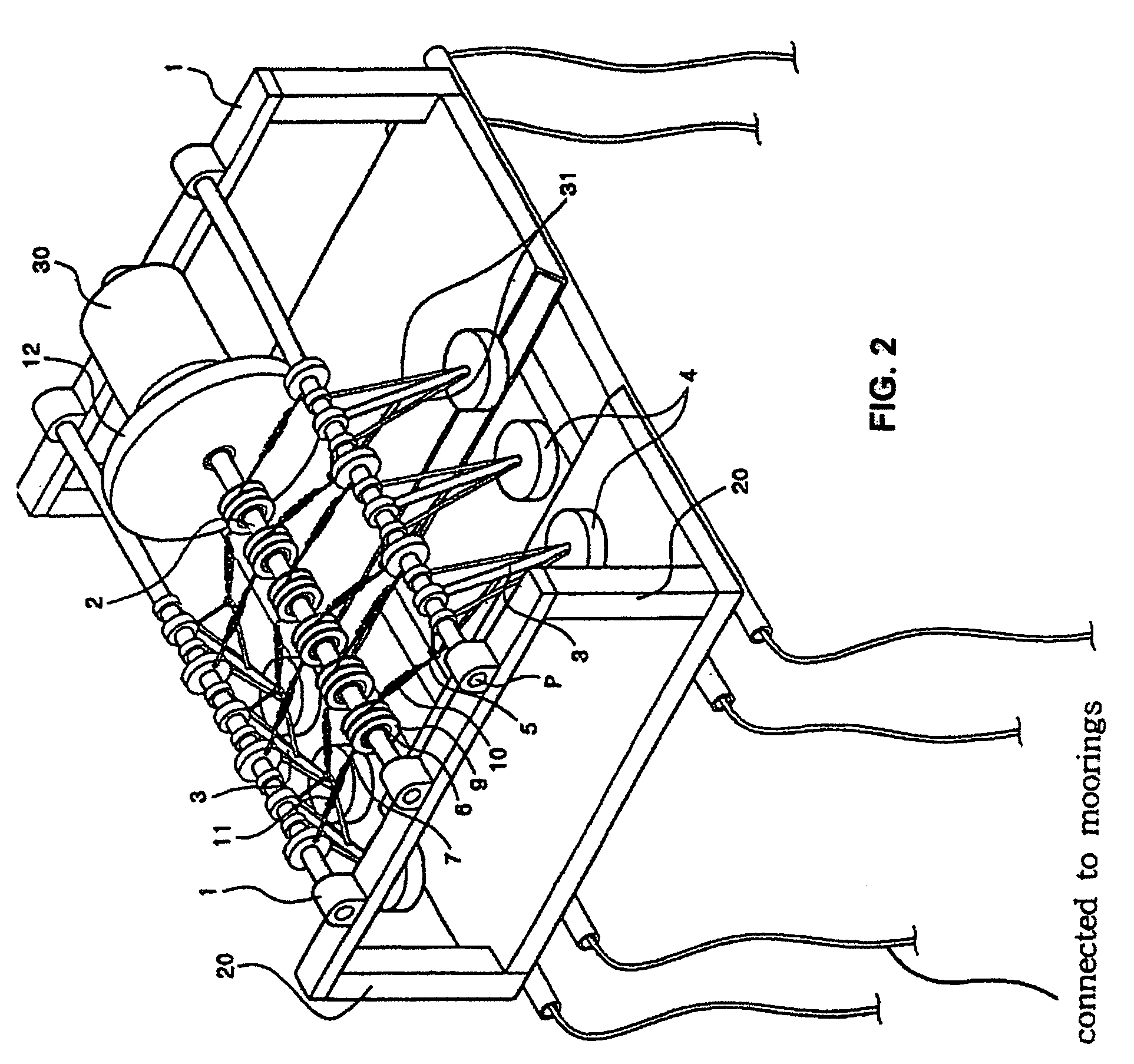
[0024]FIGS. 2 through 4 show a wave-power generation system according to a first preferred embodiment of the present invention.

[0025] As shown in figures, the wave-power generation system of the present invention includes a stationary frame 1 for supporting various components, and a float structure 20 for floating the stationary frame 1 on the sea. The stationary frame 1 consists of relatively high-strength members engaged to each other. If the stationary frame 1 is floated on the sea together with the float structure 20, a portion of the stationary frame is exposed from the surface of the sea, while a portion of the stationary frame sinks to the sea.

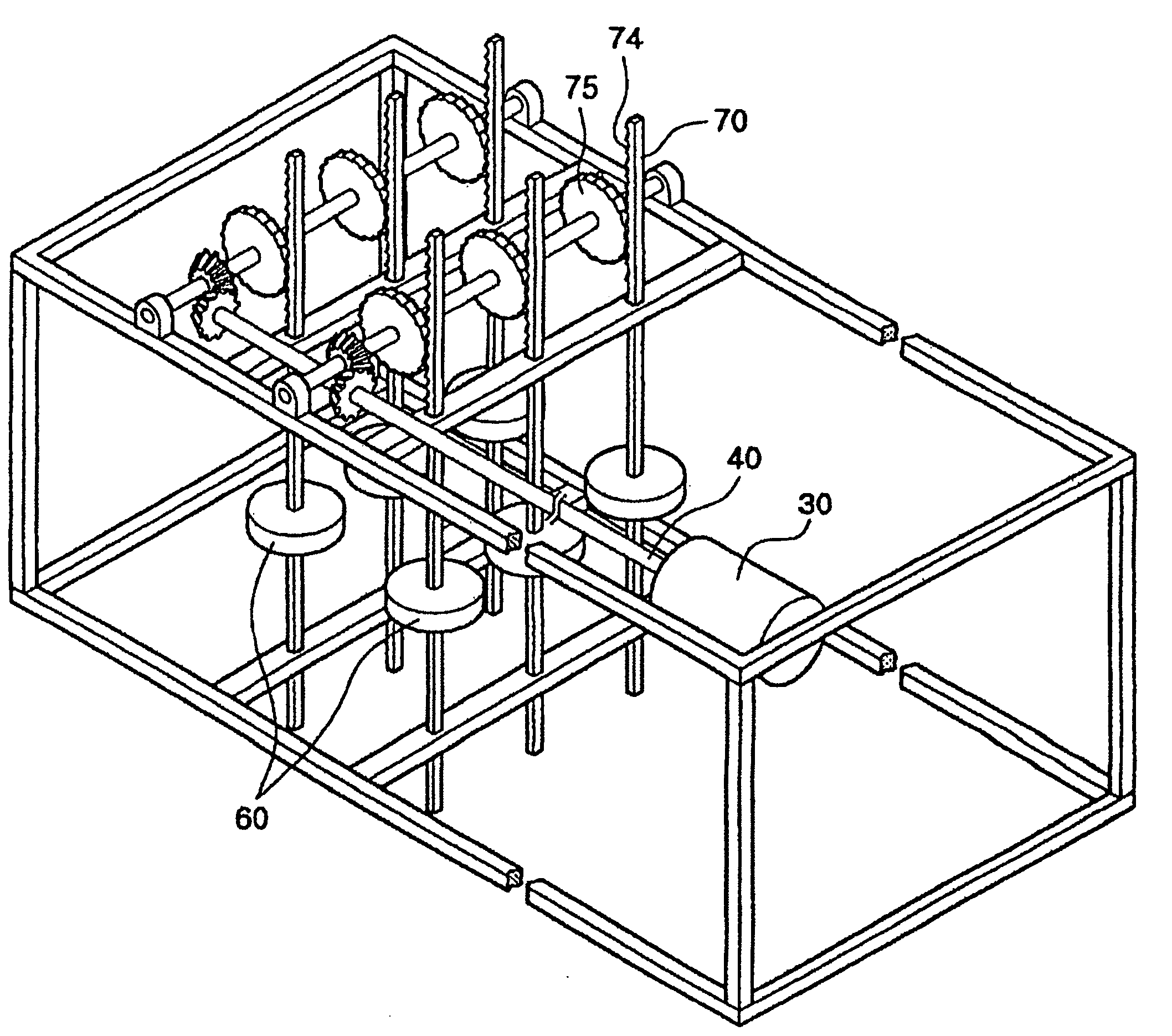
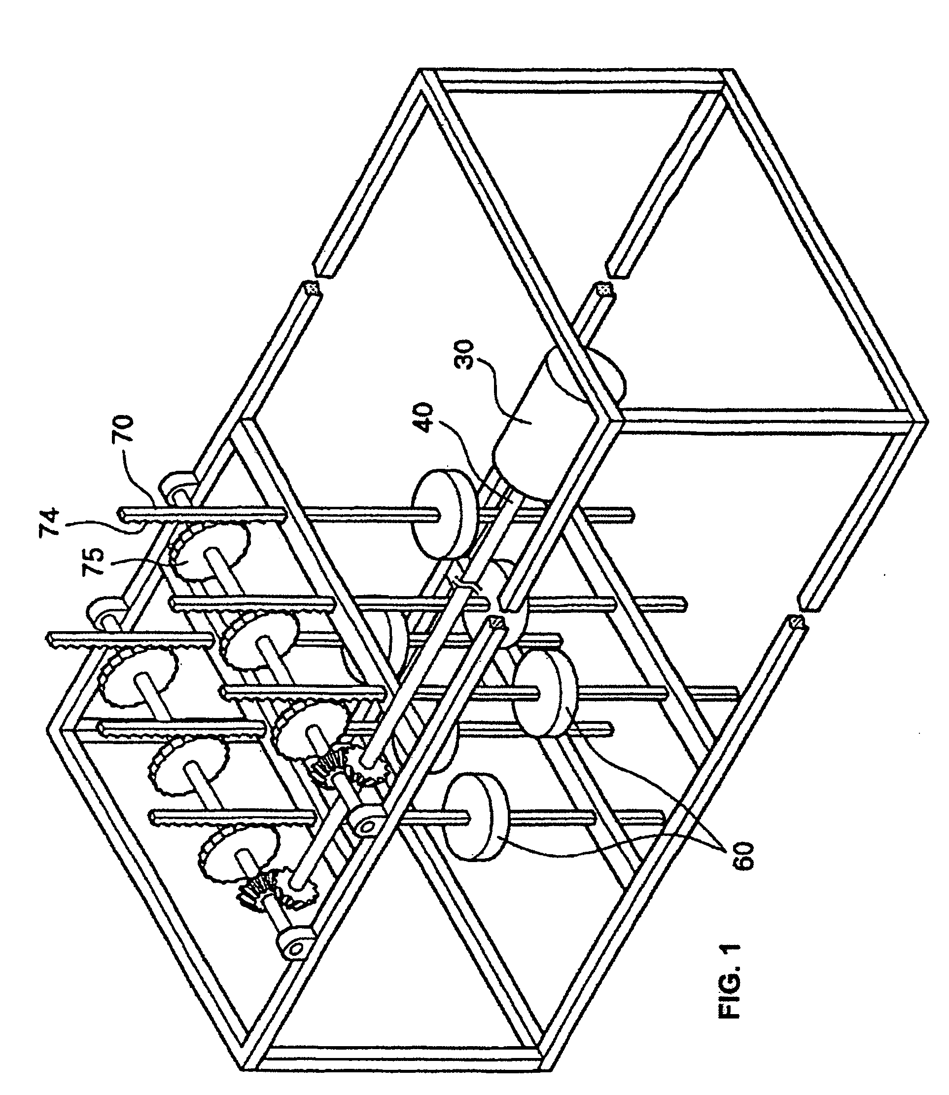
[0026] The stationary frame 1 is provided with a rotary shaft 2 of a generator which is freely rotated on the stationary frame 1. A generator 30 coupled to the rotary shaft generates the power according to the rotation of the rotary shaft 2. The stationary frame 10 includes a bearing (not shown) to rotatably support the rotary shaft 2...

second embodiment

[0037]FIG. 5 shows a wave-power generation system according to a second preferred embodiment of the present invention.

[0038] Referring to FIG. 5, the wave-power generation system of the present invention includes a stationary frame 1, a float structure 20 installed to the stationary frame 1, a generator's rotary shaft 2 rotatably installed to the stationary frame 1, and a flywheel 12 installed to the rotary shaft 2, which is similar to the first embodiment.

[0039] In this embodiment, the rotary drive 9 is coupled to the rotary shaft 2 of the generator via a one-way clutch 6. One end of a two-node link 33 is coupled to the rotary drive 9, and a float 4 is installed to a free end of the two-node link 33.

[0040] A follower of the one-way clutch 6 and a first intermediate gear 71 are installed to a first rotating drive shaft 41 installed to the stationary frame 1 in a direction parallel with the rotary shaft 2 of the generator. The first intermediate gear 71 meshes with a second gear 7...

third embodiment

[0046]FIG. 6 shows a wave-power generation system according to a third preferred embodiment of the present invention.

[0047] Referring to FIG. 6, the wave-power generation system of the present invention includes a rotary shaft 2 of a generator rotatably installed to a stationary frame 1, a rotary drive 9 coupled to the rotary shaft 2 of the generator via a one-way clutch 6, a three-node link 3 rotatably installed at a point P of the stationary frame 1, a float 4 installed to one end of the three-node link 3, and a resiliently recovering member having one end coupled to the other end of the three-node link 3 and the other end coupled to a rope 5. One end of the rope 5 is coupled to the other end of the three-node link 3, and the other end is coupled to the rotary drive 9. One end of the resilient covering member is coupled to the stationary frame 1, and the other end is coupled to the rotary drive 9. The wave-power generating system also includes the rotary drive 9 coupled to the ro...


PUM


Abstract

Disclosed is a wave-power generation system. The system includes a stationary frame, a float structure installed to the stationary frame, a rotary shaft coupled to a generator and rotatably installed to the stationary frame, a rotary drive coupled to the rotary shaft of the generator via a one-way clutch, a three-node link rotatably installed at a point P of the stationary frame, a float installed to one end of the three-node link, a rope having one end coupled to the other end of the three-node link and the other end wound around the rotary drive, a flywheel installed to the rotary shaft, and a resiliently recovering member having one end coupled to the stationary frame and the other end coupled to the rotary drive.

Description

[0001] This application is a continuation of pending International Patent Application No. PCT / KR2004 / 000874 filed on Apr. 14, 2004, which designates the United States and claims priority of Korean Application No. 10-2003-24875 filed on Apr. 19, 2003.FIELD OF THE INVENTION [0002] The present invention relates to a wave-power generation system, and more particularly, to a wave-power generation system converting kinetic energy into rotational energy using the forces of low and high tide to generate electric power. BACKGROUND ART [0003] Currently, electric power is generated by use of petroleum, fossil fuel, atomic energy, and the like. Since reserves of the petroleum and fossil fuel are limited, it should be exhausted with the passage of time. For the atomic energy, a usable period of uranium is limited because of finite exhaustion thereof and serious issue of radioactive waste. [0004] Meanwhile, wind power or solar energy has advantages in that it can be infinitely utilized and does n...

Claims


Application Information

Patent Timeline
IPC IPC(8): F03B13/12F03B13/10H02P9/04F03B13/18
CPCF03B13/1815Y02E10/38F05B2240/40Y02E10/30F03B13/12F03B13/18F03B13/188F03B13/20
Inventor YIM, MYUNG SHIK
Owner YIM MYUNG SHIK
Why Eureka
Try Eureka