Hydraulic control circuit for a continuously variable transmission

a technology of continuously variable transmission and control circuit, which is applied in the direction of friction gearing, gearing elements, gearing, etc., can solve the problems of inability to achieve the necessary balance of stability and response, and the damping required to achieve smooth transmission operation can unacceptably inhibit the response of the variator, so as to achieve stable controllable operation of the variator, maintain the stability of the variator, and respond quickly

Inactive Publication Date: 2007-10-09
TOROTRAK (DEV) LTD
View PDF9 Cites 49 Cited by
  • Summary
  • Abstract
  • Description
  • Claims
  • Application Information

AI Technical Summary

Benefits of technology

[0023]It has been found, somewhat unexpectedly, that in this way stable controllable operation of the variator can be achieved while also enabling rapid response to transients.
[0024]

Problems solved by technology

It has been found in practice that the level of damping required to achieve smooth transmission operation can unacceptably inhibit

Method used


Image

  • Hydraulic control circuit for a continuously variable transmission
  • Hydraulic control circuit for a continuously variable transmission
  • Hydraulic control circuit for a continuously variable transmission

Examples


Embodiment Construction

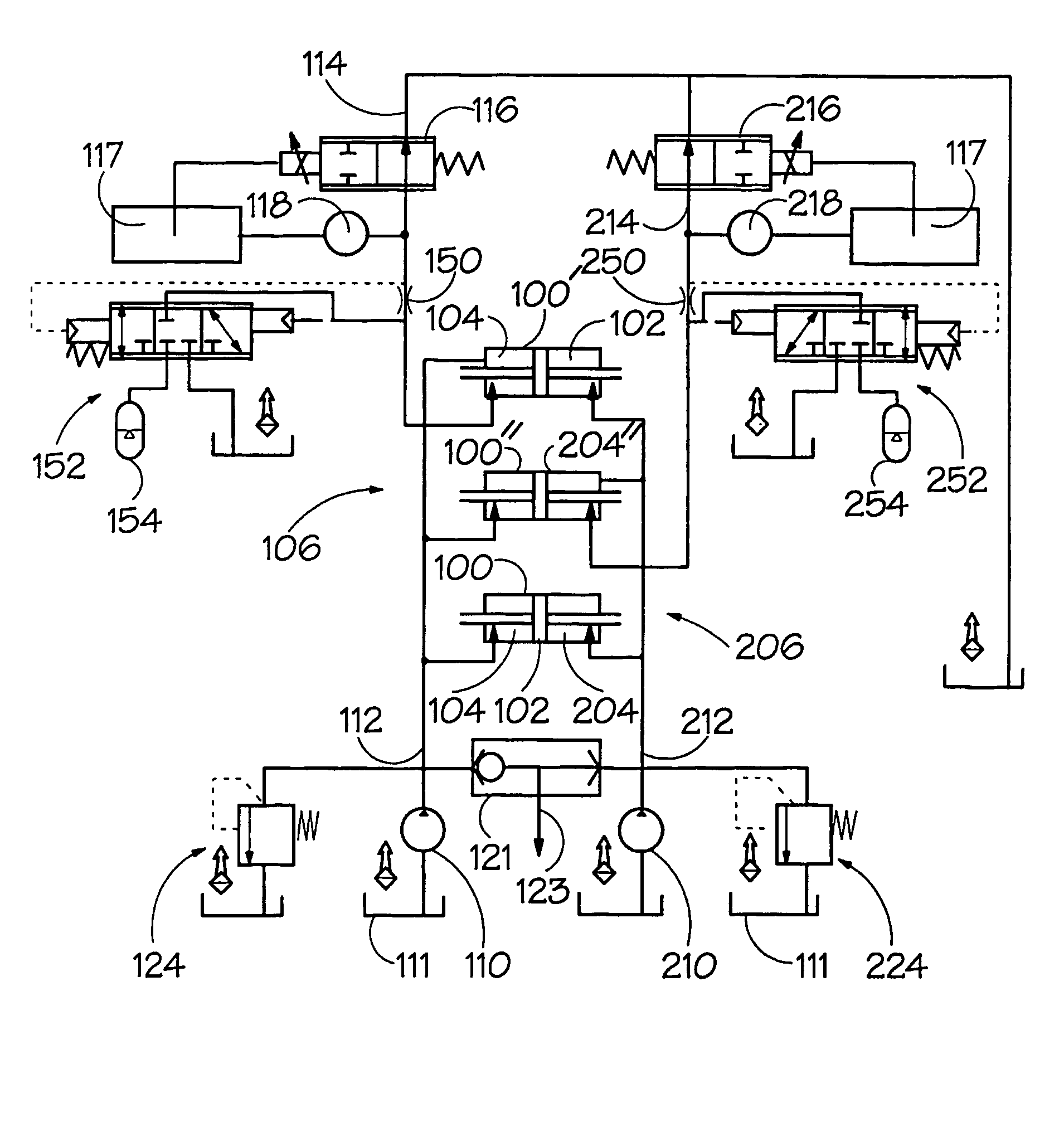
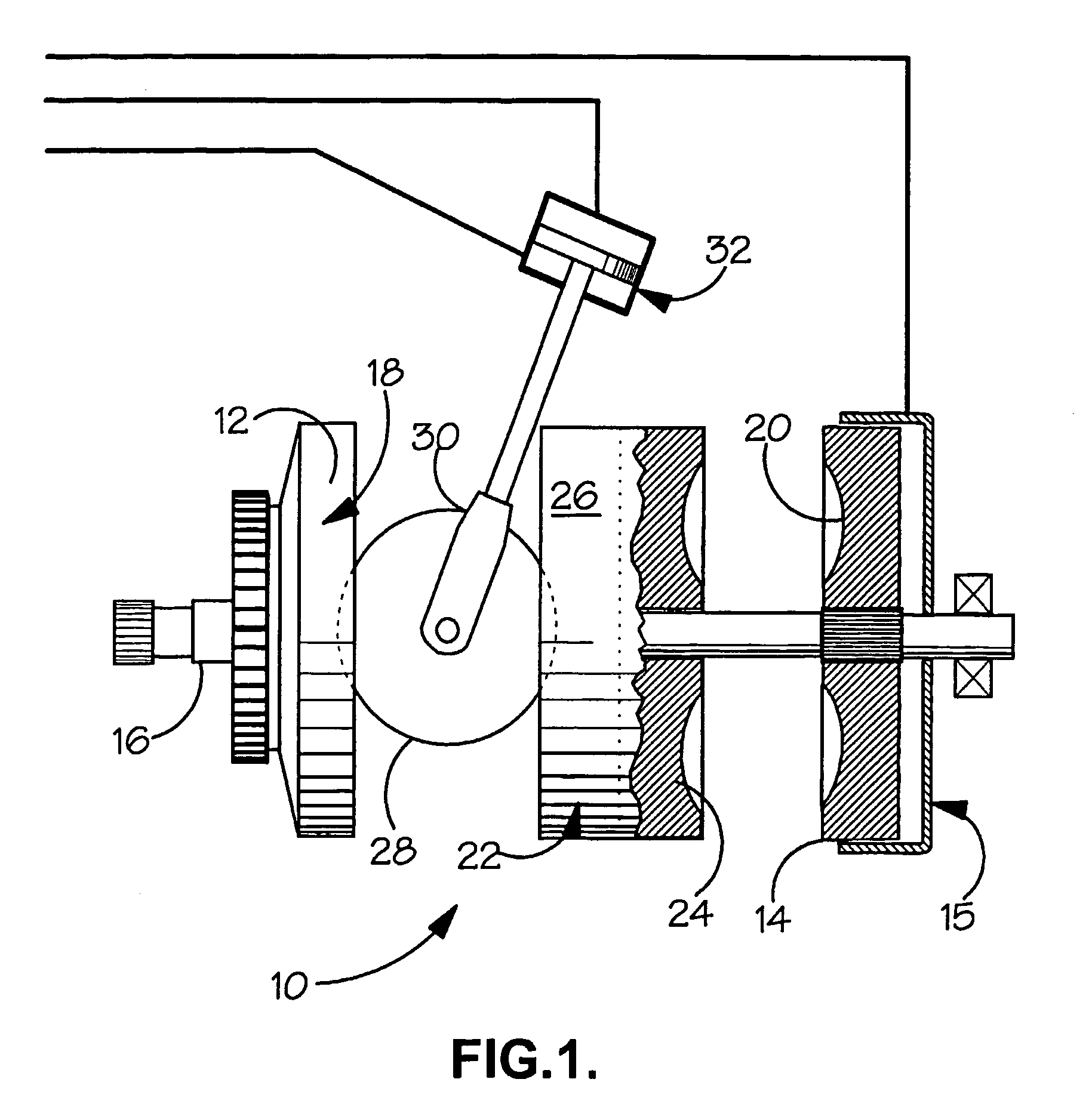
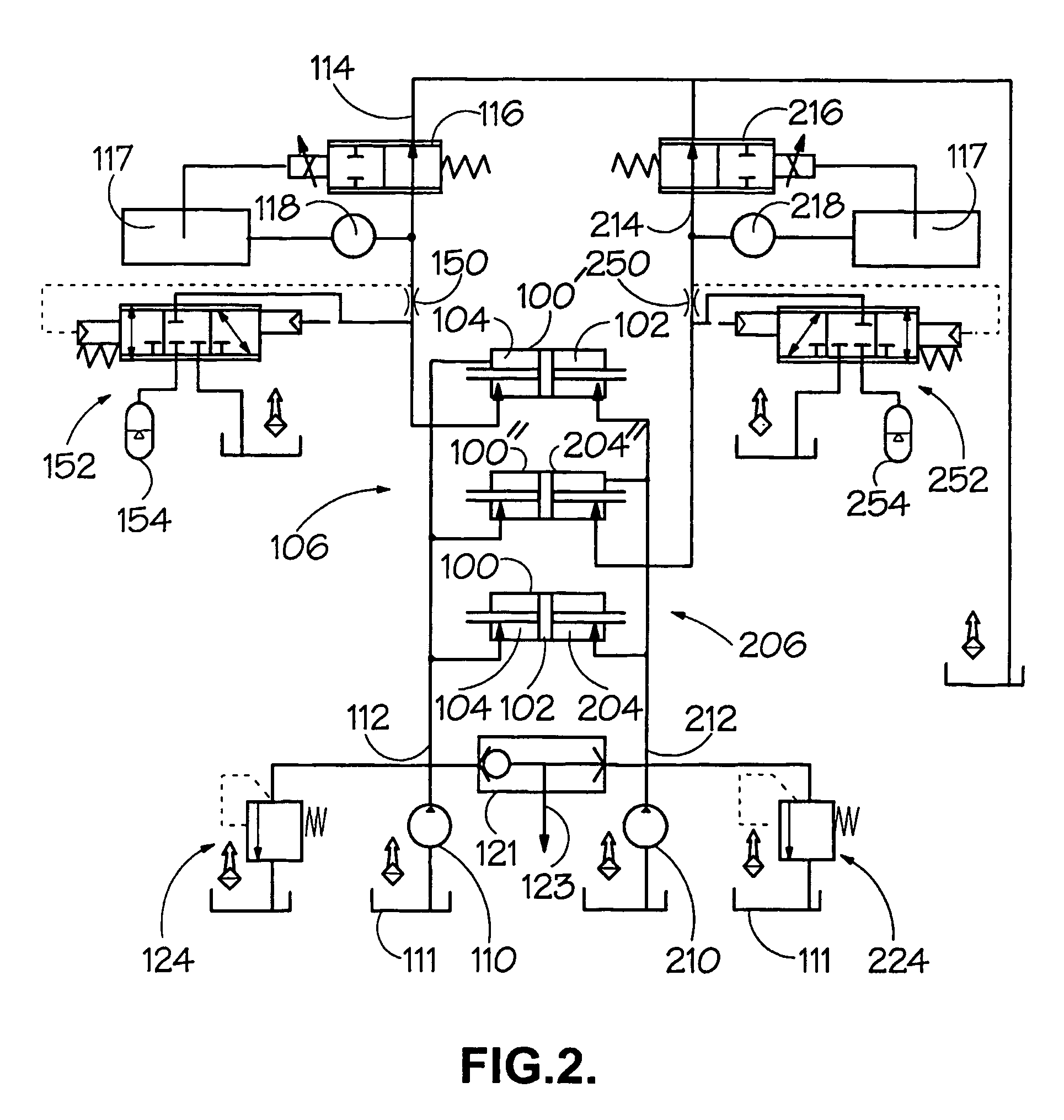
[0041]The hydraulic circuit illustrated in FIG. 2 is suitable for use with a torque control variator of the type described above with reference to FIG. 1. FIG. 2 shows, by way of illustration, a set of three hydraulic actuators 100, 100′ and 100″ (typically in a variator of the above described twin cavity type, six such actuators would be provided—three per cavity—but remaining actuators are omitted for the sake of clarity). Each actuator comprises a piston 102 whose two faces are exposed to control pressure in first and second working chambers 104, 204 so that the biasing force applied by each actuator is determined by the difference in these control pressures. Each actuator 100 is coupled to a corresponding roller / carriage assembly of the type illustrated in FIG. 1.

[0042]The hydraulic circuit provides a first flow line 106 for supplying hydraulic fluid to the first working chambers 104 and a second flow line 206 for supplying fluid to the second working chambers 204.

[0043]The firs...


PUM


Abstract

A hydraulic control circuit is disclosed for a continuously variable transmission comprising a continuously variable ratio transmission unit (“variator”) 10, the circuit comprising a supply line 106 and means (which may take the form of a pump 110) for providing a flow of pressurised fluid in the supply line, means (which may comprise a pressure control valve 116) for generating a back pressure in the supply line, and at least one connection for feeding fluid from the supply line to a hydraulic actuator 100 acting on a movable torque transmission 23-37 element (which may comprise a roller 28) of the variator 10. The valve means 152 connected to the supply line allows pressure in the supply line to be selectively modified in response to rate of flow in the supply line.

Description

BACKGROUND OF THE INVENTION[0001]1. Field of the Invention[0002]The present invention relates generally to continuously variable transmissions and more specifically to hydraulic control thereof.[0003]2. Background Art[0004]Continuously variable transmissions comprise, inter. alia an input shaft rotatable by a prime mover, an output shaft connected to vehicle wheels and a ratio varying component (hereinafter referred to as a “variator”) disposed between the input and output shafts. The variator is typically controlled by means of hydraulic pressures which can adjust the effective ratio of the variator in accordance with a driver's demands, road conditions and the like. Under steady or smoothly-changing conditions the required flows of hydraulic fluid are relatively small. However, problems can sometimes occur during rapid ratio changes of the variator, for example during braking, rapid engine acceleration or abuse conditions. During such rapid ratio changes, the flows of fluid can be...

Claims


Application Information

Patent Timeline
IPC IPC(8): F16H61/38F16H15/38F16H61/00F16H61/06F16H61/664
CPCF16H61/0021F16H61/067Y10T477/619F16H61/664F16H61/6649F16H61/068
Inventor FULLER, JOHN WILLIAM EDWARD
Owner TOROTRAK (DEV) LTD
Why Eureka
Try Eureka