
Wheelchair with suspension arms

a technology of suspension arms and wheels, which is applied in the direction of resilient suspensions, interconnection systems, medical transportation, etc., can solve the problems of severe conditions, unsatisfactory key characteristics of contemporary wheelchairs, and the respect of self-propelled wheels in the form of motorized wheelchairs, so as to improve driving comfort

Active Publication Date: 2012-10-30
INVACARE INT
View PDF363 Cites 43 Cited by
  • Summary
  • Abstract
  • Description
  • Claims
  • Application Information

AI Technical Summary

Benefits of technology

[0007]The present invention provides a wheeled conveyance with wheels independently suspended on individual suspension arms, which are arranged so that forces are directed in a way that is beneficial to the climbing of obstacles with the conveyance. Thanks to the way the suspension arms are disposed and the way forces are transmitted between them, the driving comfort is improved, especially when mounting obstacles.
[0010]The wheeled conveyance of the present invention solves the problems outlined above. As a particular advantage, the conveyance may easily be converted between indoor and outdoor use, because removal of the suspension and wheels and their replacement by respective equipment better adapted to specific outdoor or indoor use can be effected conveniently and quickly. Furthermore, the entire wheelchair may be upscaled or downscaled as desired by a particular user, by using larger or smaller wheels and suspension arms, as preferred.
[0012]In the wheelchair of the present invention, castor wheels are considered wheels which enable mobility and agility of the wheelchair while maintaining stability. Castor wheels preferably are, during normal operation of the wheelchair, constantly in touch with the ground. Castor wheels, for the purpose of the present invention, are to be differentiated from generally smaller anti-tip wheels, which often are not in touch with the ground and which have the function of preventing tilting of the wheelchair when one or more of the main wheels (motorized and castor wheels) already have lost touch with the ground.
[0018]Preferably, the wheeled conveyance of the present invention has four wheels, with a pair of rear wheels, which are motorised wheels, and a pair of front wheels, which are castor wheels. Preferably, the motorised wheels are not swivel-mounted. Thanks to the scaling properties provided by the wheeled conveyance, it is easily possible to provide front motorized wheels and rear castor wheels.

Problems solved by technology

Surveys with wheelchair users have revealed that a number of key characteristics of contemporary wheelchairs are still unsatisfactory.
A particular problem with respect to self-propelled wheeled conveyances in the form of motorized wheelchairs is reported in EP 1513479.
Accordingly, when a wheelchair comes to a quick stop, for example because a manually-operated joystick is accidentally let gone, the weight of the wheelchair is thrown forward, which may result in severe conditions.
In case that the wheelchair is located on a slope, immediate breaking may have the consequence that the wheelchair user is catapulted from the wheelchair and / or that the wheelchair is overturned completely.
The problem is exacerbated by the fact that motorised wheelchairs have a relatively short wheelbase and a relatively high centre of gravity.
The problems of stability are not only relevant when there is an immediate stop, but also when a specific obstacle needs to be overcome, for example if a stair or the sidewalk has to be mounted, or in rough, off-road terrain.
If a castor wheel of a motorised wheelchair is driven onto an obstacle, the wheelchair chassis is often lifted at the axis of the castor wheel, which results in high tensions in the chassis of the wheelchair.

Method used


Image

  • Wheelchair with suspension arms
  • Wheelchair with suspension arms
  • Wheelchair with suspension arms

Examples


Embodiment Construction

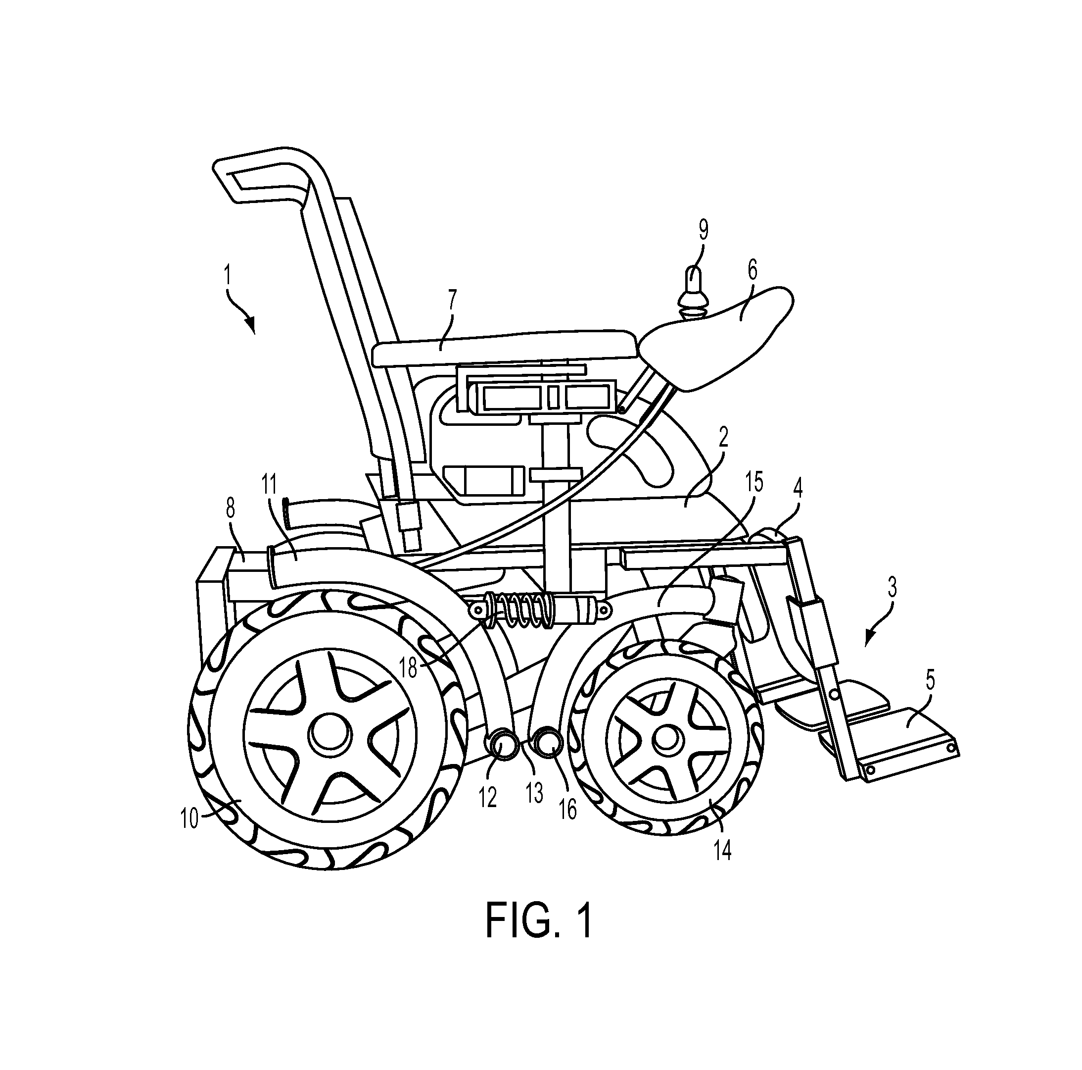
[0032]In FIG. 1, the right-side profile of a complete motorised wheelchair 1 having a pair of left and right motorised rear wheels and a pair of left and right front castor wheels is shown. A seat 2 with a backrest, a right leg-rest 3, and a right castor wheel 14 and a motorised wheel 10, respectively, can be seen. The leg-rest 3 comprises a foot-rest 5 and a calf-rest 4, as usual with wheelchairs. In the wheelchair shown, the leg-rest 3 is mounted to the seat 2. A right armrest 7, also part of the seat 2, is also visible, in front of which a steering and motion control unit 6 comprising a joystick 9 is arranged.

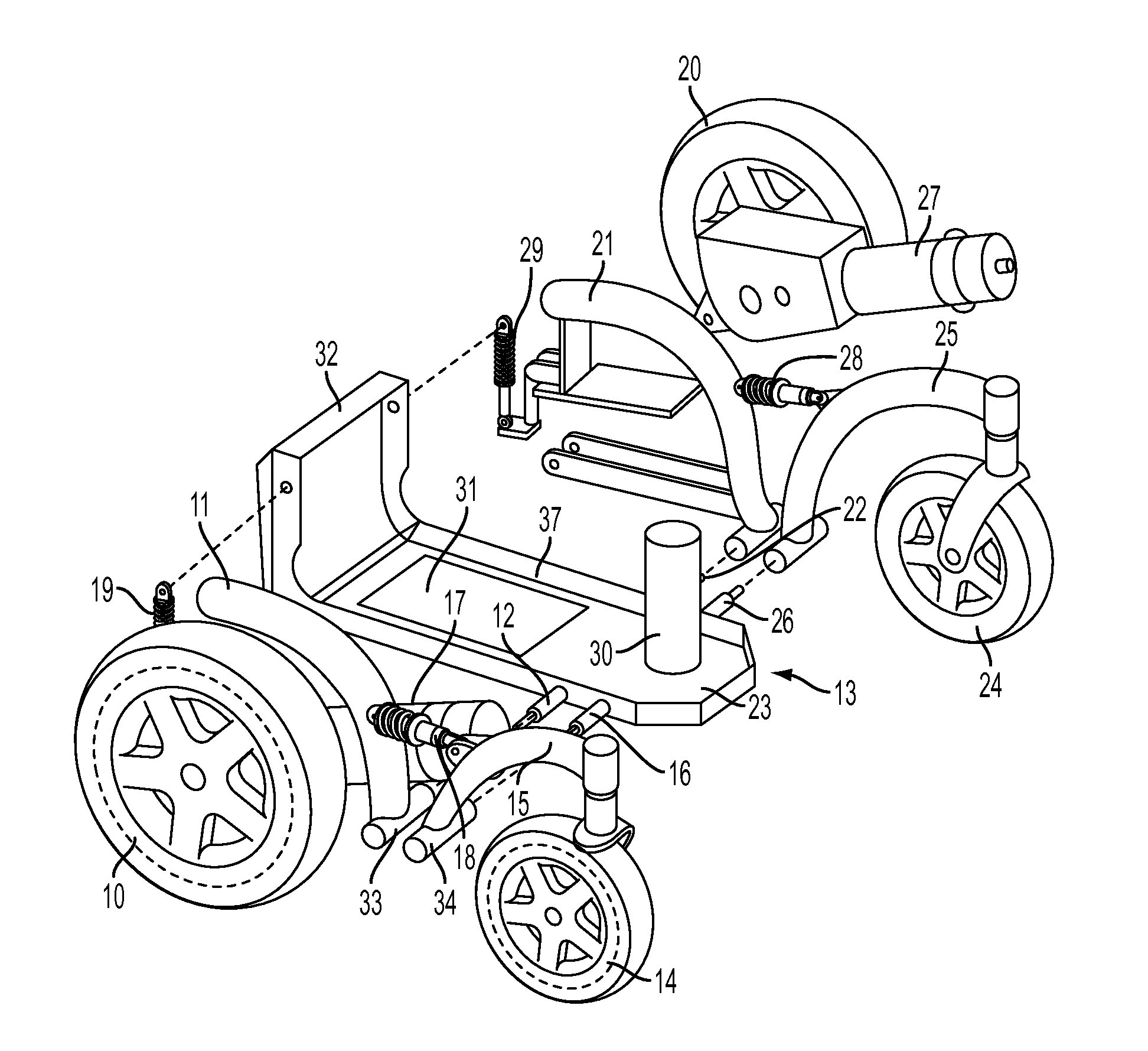
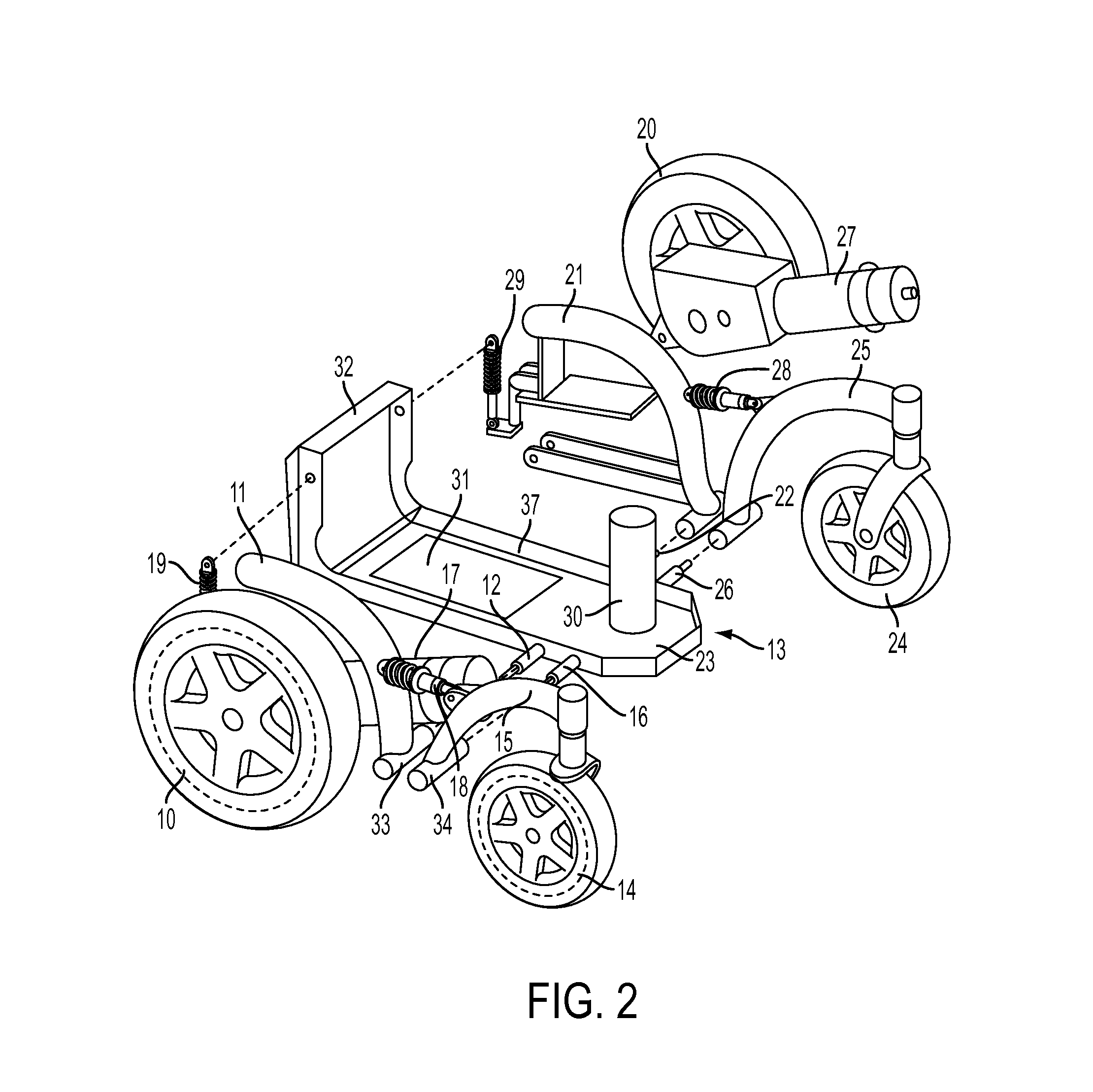
[0033]The right suspension arm 15 of the castor wheel 14 is pivotally mounted to the base 13 of the wheelchair at a pivot axis 16, and the right suspension arm 11 of the motorised wheel 10 at a pivot axis 12. The pivot axis 12 and 16 are situated next to each other, horizontally offset. A small portion of the base 13, to which the suspension arms are pivotally fixed at the p...


PUM


Abstract

Each wheel (10, 14 / 20, 24) of the wheelchair (1) is fixed to a suspension arm (11,15 / 21, 25). A force transmitting device, for example a spring and damper of the wheelchair unit, directly connects two suspension arms situated on the same side of the wheeled conveyance, so that forces exerted on one of the wheels are transmitted to the other wheel. In this way, obstacles can more conveniently be overcome. A further advantage of the wheelchair is that it can be easily upscaled and driving properties can be adjusted according to a user's preferences.

Description

[0001]This application is the U.S. national phase entry of PCT / IB2008 / 050111, with an international filing date of Jan. 14, 2008, which claims the benefit of European patent application serial no. 07100483.2, filed Jan. 12, 2007, the entire disclosures of which are fully incorporated herein by reference.TECHNICAL FIELD[0002]The present invention relates to a motorised wheelchair. The wheels of the wheelchair are suspended at suspension arms in way that driving comfort is increased and tensions in the base of the wheelchair are reduced.PRIOR ART AND THE PROBLEM UNDERLYING THE INVENTION[0003]Surveys with wheelchair users have revealed that a number of key characteristics of contemporary wheelchairs are still unsatisfactory. For example, driving comfort with state of the art wheelchairs needs to be improved. With respect to the indoor use, it is desirable that a wheelchair is as narrow as possible. On the other hand, for motorised wheelchairs used outdoors, good traction is a relevant ...

Claims


Application Information

Patent Timeline
Patent Type & Authority Patents(United States)
IPC IPC(8): B60K1/00A61G5/04
CPCA61G5/045A61G5/06A61G2005/1078A61G2203/14A61G5/1078
Inventor LINDENKAMP, HORSTFARWER, JENS
Owner INVACARE INT
Learn More