Pallet

a technology of pallets and pallets, applied in the field of pallets, can solve the problems of large amount of space required for storing pallets, unstable stacks, and high stacks, and achieve the effect of improving alignment and engagement with handling equipment and articles

Inactive Publication Date: 2009-10-27
SNYDER PROD
View PDF84 Cites 49 Cited by
  • Summary
  • Abstract
  • Description
  • Claims
  • Application Information

AI Technical Summary

Benefits of technology

[0009]The present invention is directed to a pallet, and in particular to a pallet having improved alignment and engagement with handling equipment and articles being supported.
[0010]The pallet has a substantially rectangular configuration with a planar upper deck having channels formed therein. The upper surface of the deck also includes recesses aligning with legs or feet of other similar pallets to provide for nesting of the pallets when stacked while empty. The pallets of the present invention include runners extending along opposed sides of the pallet. The upper surface of the deck has slight recessed portions along opposed sides to accommodate the runners for stacking. The recessed portions allow for engagement of the alignment portions with the feet as well as accommodating the runners. With this configuration, nesting is accomplished while maintaining stability without deep recesses that could damage articles stored on the pallet.
[0012]In one aspect of the present invention, the side of the pallet has alignment sections. The alignment sections protrude outward and are slightly thicker than the sidewalls of the pallet. The alignment sections allow for engagement with pallet handling equipment and precise positioning of the pallets relative to the equipment. As molded pallets cannot obtain the tolerances sought with conventional rotational molding techniques, the alignment sections are made through an improved method. According to the present invention, the pallet is molded with the alignment sections protruding outward at approximately the preselected positions and distances. The alignment sections are molded with greater thickness than the sidewalls and protrude outward, with excess material provided over the final material needs. In this manner, precise equipment can be utilized to machine the alignment sections to remove excess material and achieve tolerances and distances within those required for alignment with precise handling equipment. The alignment sections avoid problems with waves from machining an entire side of the pallet.

Problems solved by technology

However, the stacks may become very high and the amount of space required for storing the pallets may be quite extensive.
In addition, the pallets may easily slide relative to one another, making the stacks very unstable and creating a danger from pallets sliding and falling.
However, some articles, such as sheets of paper, are supported on the pallet, the weight of the paper mass may cause damage to the bottom sheets over the indentations.
Such indentations in the paper may make some of the paper unsuitable for use, thereby increasing cost.
Providing a surface that does not damage material such as paper while also locking pallets together when stacked become much more difficult when elongate runners are utilized due to their shape and size.
Moreover, providing easy access for pallet jacks and forklifts when runners are utilized while maintaining sufficient support provides special design challenges.
However, the pallet may not be compatible with all handling equipment.
Problems may arise, as molded patents typically cannot meet some of the tolerances required to properly align the pallets.
Utilizing a method to machine the sides of the pallets may create waves along the side of the pallet, requiring further machining and in some instances, ruining the pallet.
Further problems may arise when pallets are utilized with conveyors having rollers.
The edges of the pallets may abut the roller at a poor engagement angle and make movement more difficult or less smooth, due to the engagement between the pallet and roller not being sufficiently gradual.

Method used


Image

  • Pallet
  • Pallet
  • Pallet

Examples


Embodiment Construction

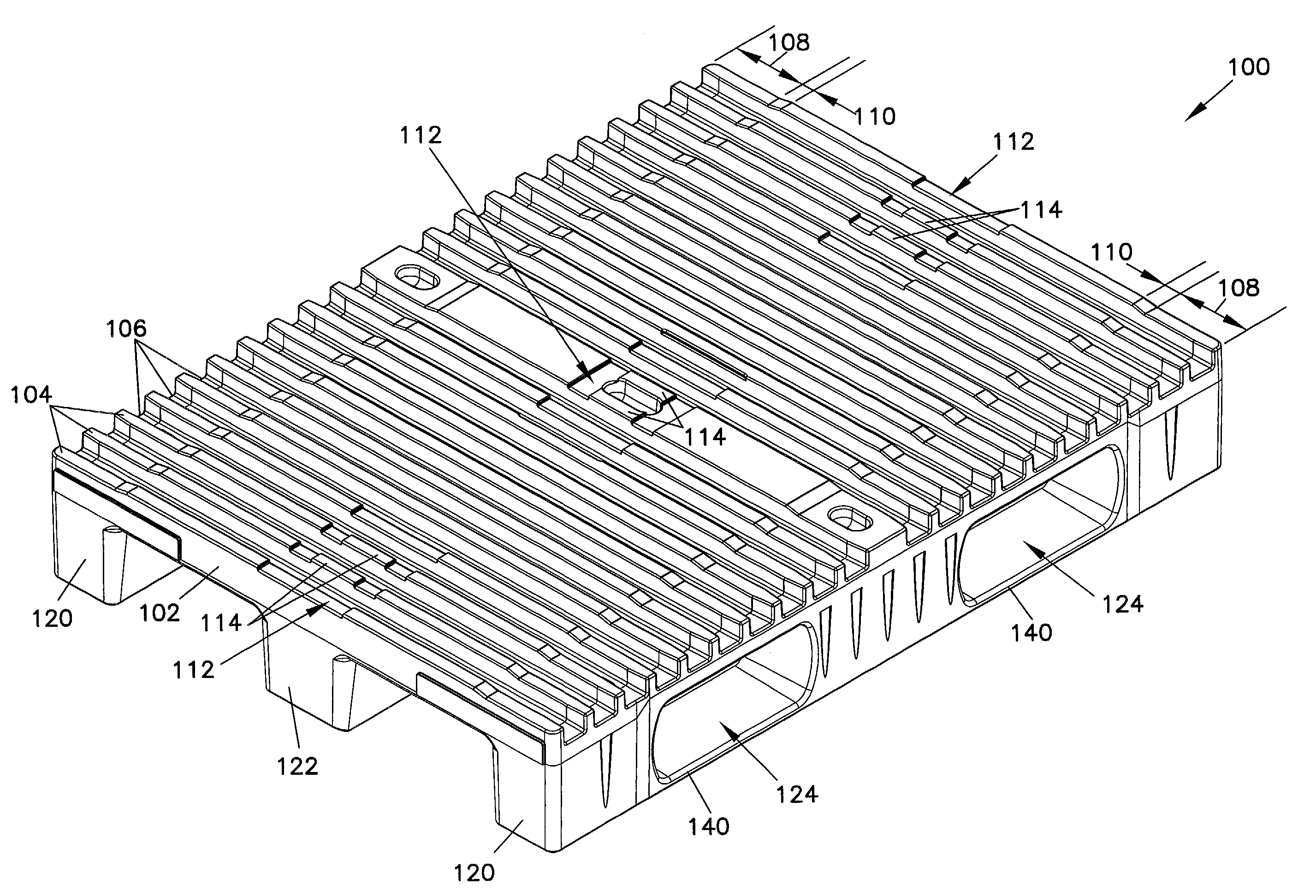
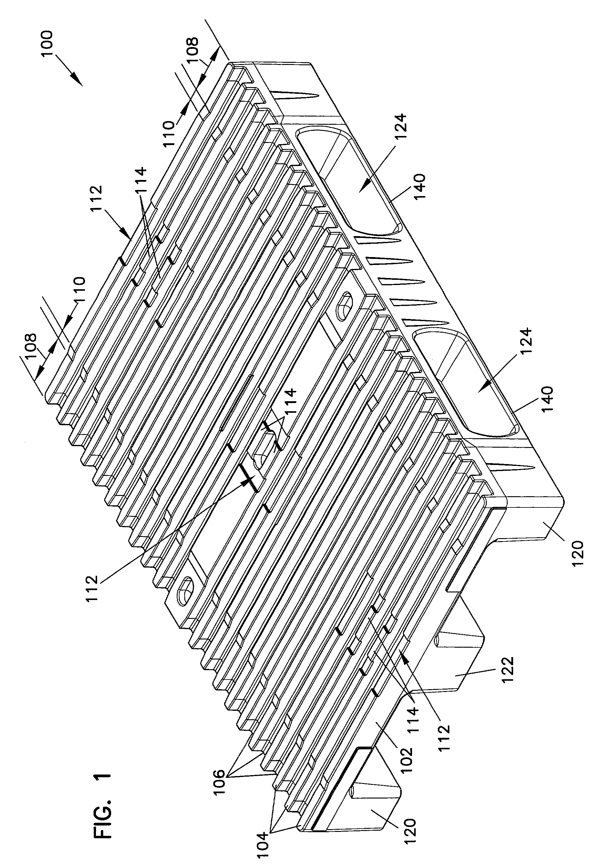
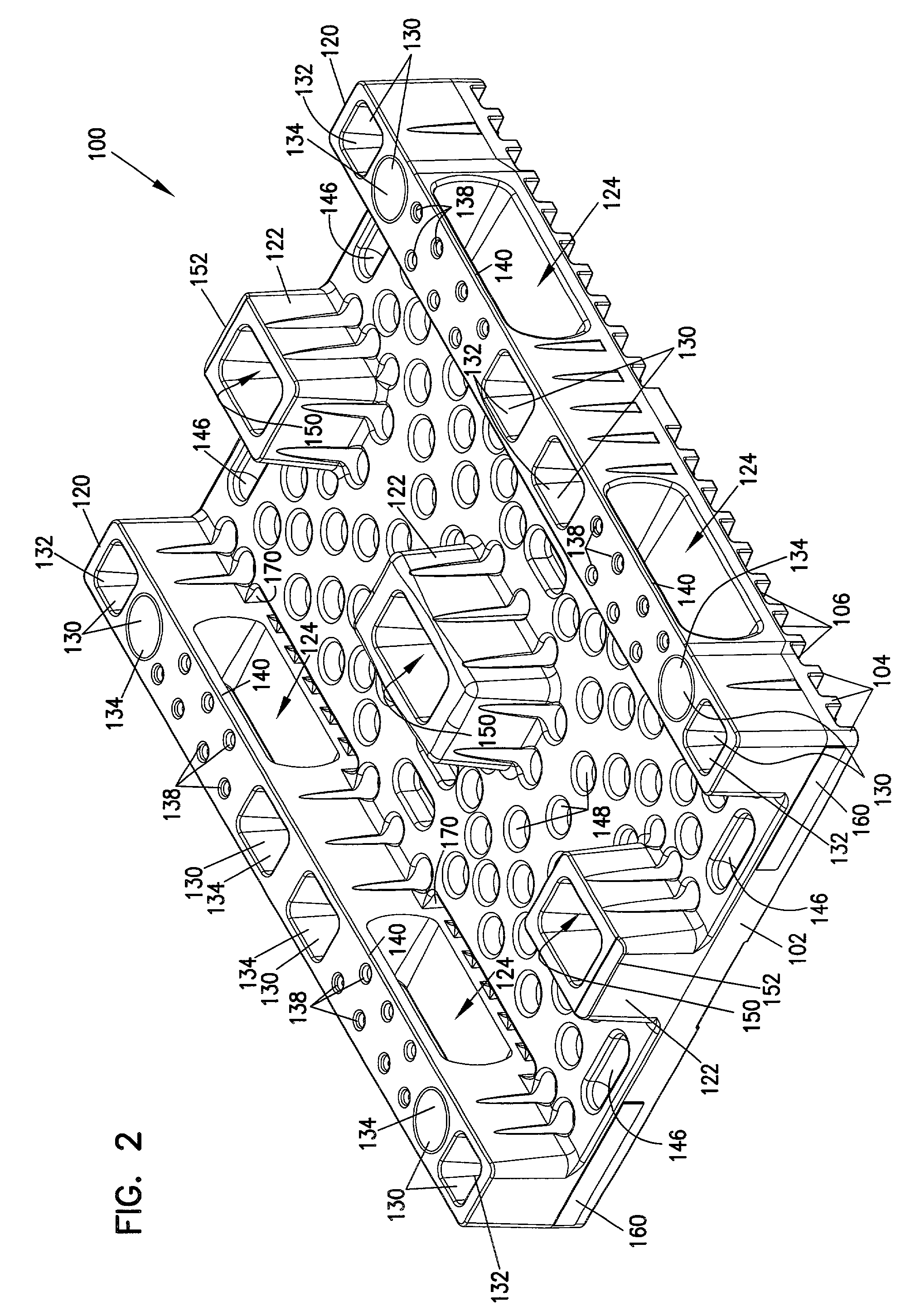
[0025]Referring now to the drawings, and in particular to FIG. 1, there is shown a pallet, generally designated 100. The pallet 100 includes a typically rectangular deck having parallel ribs 104 extending across the width of the deck 102. The ribs 104 form channels 106 there between, which widen from the center to the edges of the deck 102 while the centerlines of the channels 106 remain spaced equidistant from one another in a preferred embodiment. The ribs 104 are tapered at their ends to allow insertion of tines for lifting objects from the upper surface of the deck 102. The upper surface of the deck 102 also includes recesses 112 having raised center portions 114 that extend upward to the upper surface of the deck 102. The recesses 112, as best shown in FIG. 3, receive the bottoms of legs 122, best shown in FIG. 4, to provide for nesting of the pallets 100 when stacked while empty. The legs 122, also commonly called feet, include bottom recesses 150 that receive the center porti...


PUM


Abstract

A pallet includes a deck and support members extending from an underside of the deck. The deck has alignment recesses as well as lowered portions along both sides of the deck for receiving the feet and runners supporting the deck to achieve nesting when stacked. The support members include two runners with orifices extending there through and aligned to accommodate pallet jacks and forklifts. The orifices have straps extending underneath the orifices to provide structural support while allowing for insertion of pallet jacks and their wheels. The pallet has feet between the runners and spaced so that the underside of the deck is unobstructed in the area intermediate the orifices providing for four way insertion of pallet jack support units. The pallet has alignment sections machined into the sides of the pallet to provide for precise alignment with pallet handling equipment.

Description

BACKGROUND OF THE INVENTION[0001]1. Field of the Invention[0002]The present invention relates to a pallet and in particular, to a pallet providing improved positioning features and a support system that provides for easier handling and access by handling equipment.[0003]2. Description of the Prior Art[0004]Pallets for supporting and moving various types of articles are well known. Pallets are made from many materials, including wood, metal, fiberglass or plastic, depending on the intended use and environment in which the pallets are used. Pallets generally provide a planar upper support surface and are adapted for use with many types of loading equipment, lifting by cranes, forklifts, hand trucks or other specialized handling equipment.[0005]Pallets are typically constructed with a planar supporting surface having runners or sets of legs, often referred to as feet, extending downward there from to elevate the articles being supported off the ground to prevent moisture, dirt and othe...

Claims


Application Information

Patent Timeline
Patent Type & Authority Patents(United States)
IPC IPC(8): B65D19/00B65D19/38
CPCB65D19/0036B65D2519/0096B65D2519/00069B65D2519/00268B65D2519/00288B65D2519/00298B65D2519/00318B65D2519/00333B65D2519/00338B65D2519/00407B65D2519/00412B65D2519/00781B65D2519/00791B65D2519/00796B65D2519/00805B65D2519/00034
Inventor ELDER, ANDREW W.SKINNER, WILLIAM J.BADGER, BOBBY G.
Owner SNYDER PROD
Why Eureka
Try Eureka