Back Stress Reducing Kneeling Device

a technology of back muscle stress and kneeling device, which is applied in the field of kneeling mats, can solve the problems of user knee soreness and/or knee fatigue, knee cushion may slide out on the floor, and none of them incorporate a feature that will reduce back muscle stress

Inactive Publication Date: 2008-09-18
PFEIFFER CARL M
View PDF11 Cites 6 Cited by
  • Summary
  • Abstract
  • Description
  • Claims
  • Application Information

AI Technical Summary

Benefits of technology

[0022]AN OBJECT of the present invention is to provide a bath aid that avoids the disadvantages of the prior art.

Problems solved by technology

The main problem with conventional cushion pads are none of them incorporate a feature that will reduce back muscle stress.
Another problem with conventional cushion pads is the user may get sore knees and / or knee fatigue.
Another problem with conventional cushion pads is the knee cushion may slide out on the floor if the user leans too far forward.
Customer reviews of existing cushion pads on the market frequently state shortcomings of discomfort, causing backaches, weight limits, safety issues and cleaning difficulties.
Furthermore, even though these innovations may be suitable for the specific individual purposes to which they address, accordingly, they would not be suitable for the purposes of the present invention as heretofore described.

Method used


Image

  • Back Stress Reducing Kneeling Device
  • Back Stress Reducing Kneeling Device
  • Back Stress Reducing Kneeling Device

Examples


Embodiment Construction

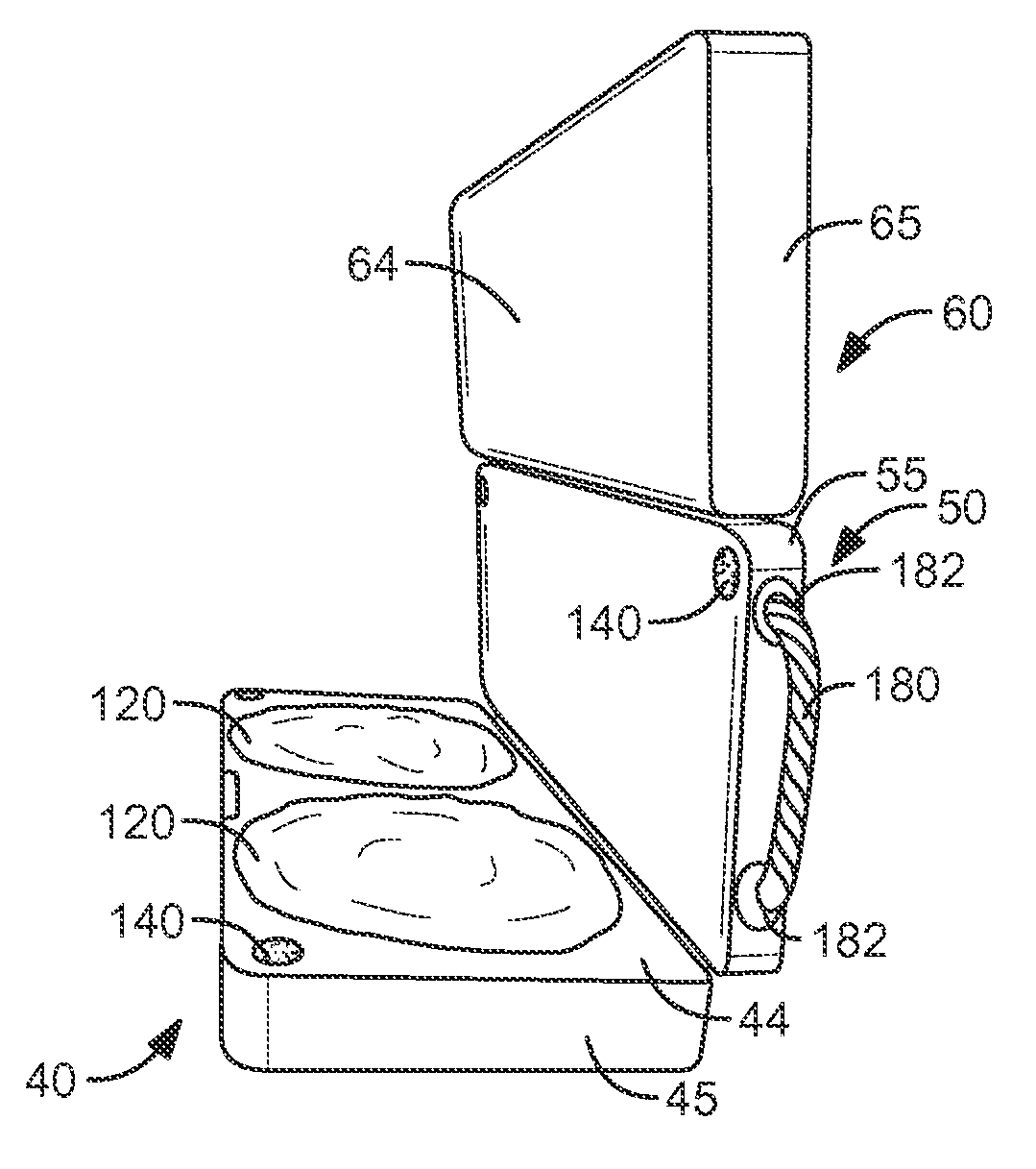
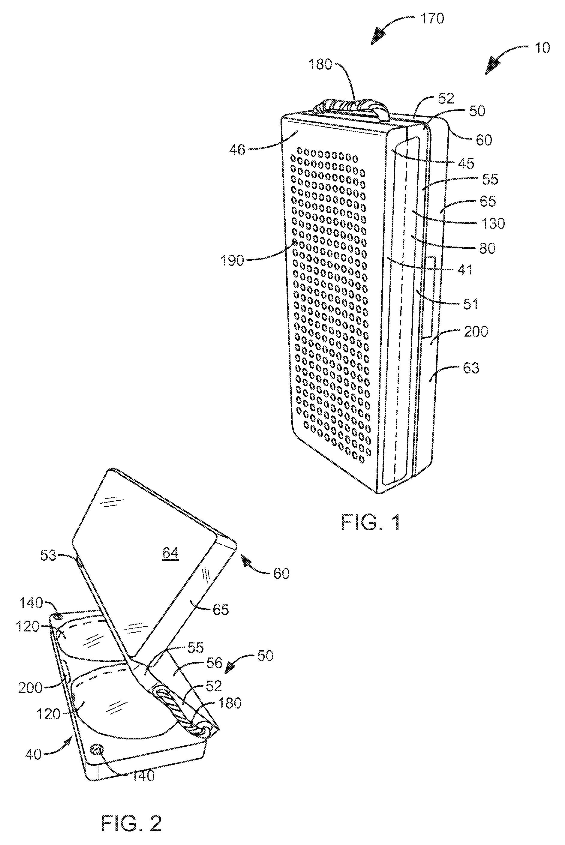
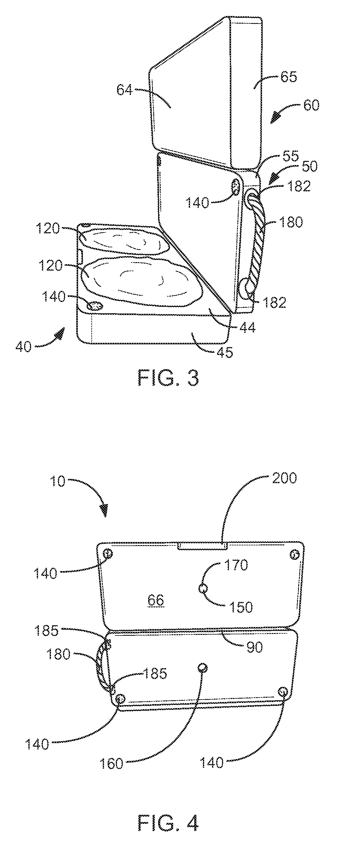
[0033]Referring now to the figures, in which like numerals indicate like parts, and particularly to FIGS. 1 through 6, the present invention, will be discussed with reference thereto. A bath aid 10 is provided for supporting a person 20 kneeling at a bathtub 30. The bath aid 10 comprises a lower pad 40 that has a top surface 44, a bottom surface 46, and at least one peripheral edge 45 connecting the top and bottom surfaces 44, 46. A middle pad 50 has a top surface 54, a bottom surface 56 and at least one peripheral edge 55 connecting the top and bottom surfaces 54, 56. An upper pad 60 has a top surface 64, a bottom surface 66 and at least one peripheral edge 65 connecting the top and bottom surfaces 64. 66. The upper pad 60 includes a tub attachment mechanism 70 fixed to the bottom surface 66 thereof. A first hinge mechanism 80 pivotally connects a front edge 41 of the lower pad 40 to a lower edge 51 of the middle pad 50, while a second hinge mechanism 90 pivotally connects an upper...


PUM


Abstract

A bath aid is provided for supporting a person kneeling at a bathtub. The bath aid comprises a lower pad, a middle pad, and an upper pad which includes a tub attachment mechanism fixed to a bottom surface thereof. A first hinge mechanism pivotally connects a front edge of the lower pad to a lower edge of the middle pad, while a second hinge mechanism pivotally connects an upper edge of the middle pad to a lower edge of the upper pad. The bottom surface of the lower pad rests on a floor surface, while the bottom surface of the upper pad may be fixed to the bathtub by the tub attachment mechanism when in an open position.

Description

CROSS-REFERENCE TO RELATED APPLICATIONS[0001]This application claims the benefit of U.S. Provisional Patent Application 60 / 895,380, filed on Mar. 16, 2007, and incorporated herein by reference.STATEMENT REGARDING FEDERALLY SPONSORED RESEARCH AND DEVELOPMENT[0002]Not Applicable.FIELD OF THE INVENTION[0003]This invention relates to mats, and more particularly to a kneeling mat for use with a bathtub.DISCUSSION OF RELATED ART[0004]Numerous innovations for cushion pads have been provided in the prior art that will be described. Even though these innovations may be suitable for the specific individual purposes to which they address, they differ from the present invention.[0005]A FIRST EXAMPLE, U.S. Patent Office Document No. 4,356,575, issued on Nov. 2, 1982, to Terry teaches a cushioned or padded kneeling appliance particularly adapted for use in association with a bathtub when it is desired to reach into the interior area of the bathtub to perform some utilitarian function, such as bat...

Claims


Application Information

Patent Timeline
Patent Type & Authority Applications(United States)
IPC IPC(8): A47K3/024A47C7/50A47K3/00
CPCA47K3/001A47C16/04
Inventor PFEIFFER, CARL M.
Owner PFEIFFER CARL M
Why Eureka
Try Eureka