
Optimal Rasterization for Maskless Lithography

Inactive Publication Date: 2008-09-18
ASML NETHERLANDS BV +1
View PDF7 Cites 31 Cited by
  • Summary
  • Abstract
  • Description
  • Claims
  • Application Information

AI Technical Summary

Benefits of technology

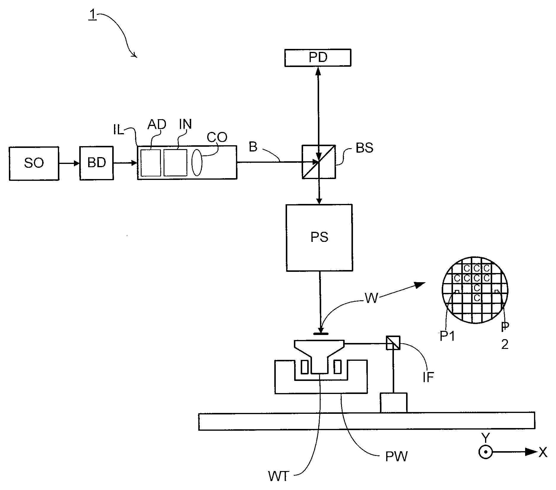
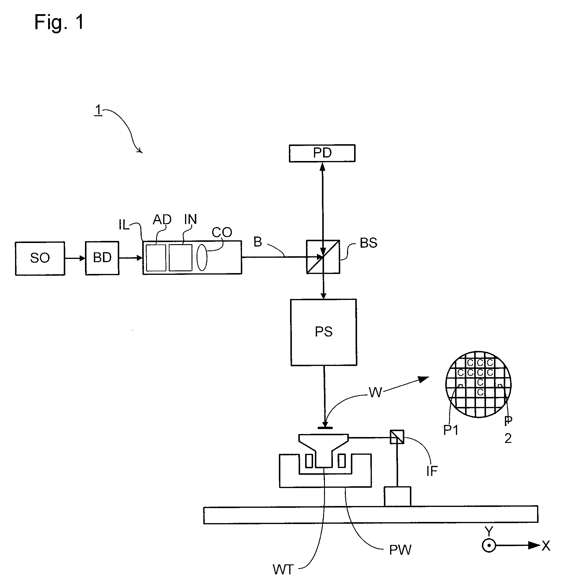
[0010]In one embodiment, there is provided a lithographic apparatus comprising one or more arrays of individually controllable elements, a projection system, and a controller. The one or more arrays of individually controllable elements are configured to modulate a beam of radiation. The projection system is configured to project the modulated beam of radiation onto a substrate. The controller is configured to control the lithographic apparatus, such that it exposes a pattern of radiation on the substrate. The pattern comprises a plurality of regions in which a common

Problems solved by technology

However, the data processing architecture required to convert a desired pattern into the necessary control signals for a programmable patterning device is a significant portion of the cost of a maskless lithographic apparatus.

Method used


Image

  • Optimal Rasterization for Maskless Lithography
  • Optimal Rasterization for Maskless Lithography
  • Optimal Rasterization for Maskless Lithography

Examples


Embodiment Construction

[0023]This specification discloses one or more embodiments that incorporate the features of this invention. The disclosed embodiment(s) merely exemplify the invention. The scope of the invention is not limited to the disclosed embodiment(s). The invention is defined by the claims appended hereto.

[0024]The embodiment(s) described, and references in the specification to “one embodiment”, “an embodiment”, “an example embodiment”, etc., indicate that the embodiment(s) described can include a particular feature, structure, or characteristic, but every embodiment cannot necessarily include the particular feature, structure, or characteristic. Moreover, such phrases are not necessarily referring to the same embodiment. Further, when a particular feature, structure, or characteristic is described in connection with an embodiment, it is understood that it is within the knowledge of one skilled in the art to effect such feature, structure, or characteristic in connection with other embodiment...


PUM


Abstract

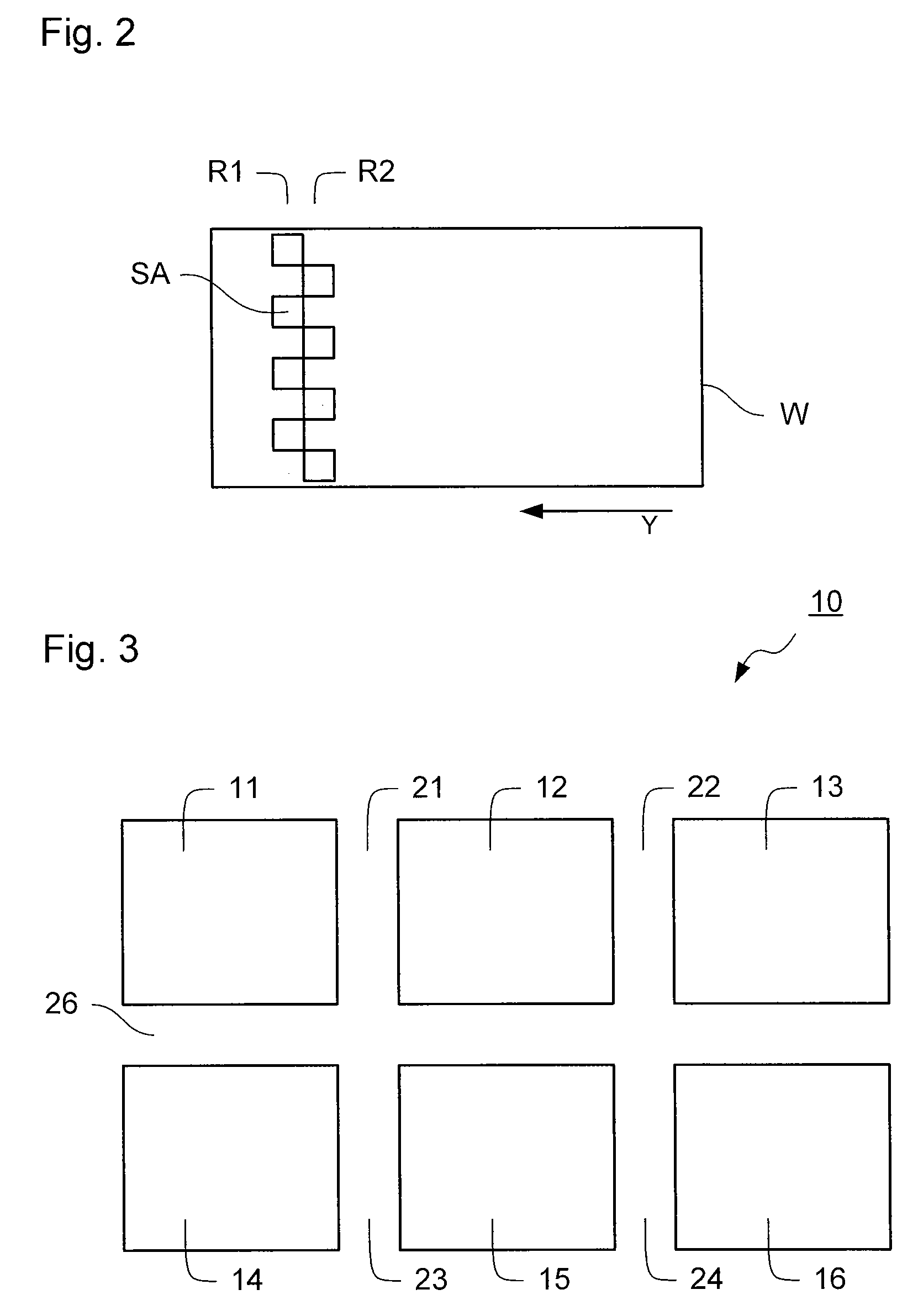
A lithographic system is provided in which an extent of overlap between pattern sections is adjusted in order to match a size of a pattern section to a size of a repeating portion of the pattern to be formed.

Description

BACKGROUND[0001]1. Field of the Invention[0002]The present invention relates to a lithographic system and device manufacturing method for optimizing rasterization in maskless lithography.[0003]2. Related Art[0004]A lithographic apparatus is a machine that applies a desired pattern onto a substrate or part of a substrate. A lithographic apparatus can be used, for example, in the manufacture of flat panel displays, integrated circuits (ICs) and other devices involving fine structures. In a conventional apparatus, a patterning device, which can be referred to as a mask or a reticle, can be used to generate a circuit pattern corresponding to an individual layer of a flat panel display (or other device). This pattern can be transferred onto all or part of the substrate (e.g., a glass plate), by imaging onto a layer of radiation-sensitive material (e.g., resist) provided on the substrate.[0005]Instead of a circuit pattern, the patterning device can be used to generate other patterns, for ...

Claims


Application Information

Patent Timeline
IPC IPC(8): H01L29/00G03B27/54G03C1/00G06F3/038
CPCG03F7/70291G03F7/70358G03F7/70791G03F7/70508G03F7/70475
Inventor TROOST, KARS ZEGERHINTERSTEINER, JASON DOUGLASCUPERUS, MINNECHILOV, KAMEN HRISTOVZIMMERMAN, RICHARD CARLVAN T. WESTEINDE, RONNIE FLORENTIUS
Owner ASML NETHERLANDS BV
Learn More