
Image decoding apparatus and image decoding method

a decoding apparatus and image technology, applied in the field of image decoding apparatus and image decoding method, can solve the problems of deteriorating decoding performance and description of the technique of suppressing the increase in the number of decoding cycles

Inactive Publication Date: 2008-09-18
KK TOSHIBA
View PDF5 Cites 1 Cited by
  • Summary
  • Abstract
  • Description
  • Claims
  • Application Information

AI Technical Summary

Problems solved by technology

Consequently, as the number of non-zero coefficients (that is, the number of coefficient data) increases, the number of cycles of processing the residual block becomes larger, thus deteriorating decoding performance.
However, in Japanese Patent Application Laid-Open No. 2006-135786, there is no description of the technique of suppressing the increase in the number of decode cycles.

Method used


Image

  • Image decoding apparatus and image decoding method
  • Image decoding apparatus and image decoding method
  • Image decoding apparatus and image decoding method

Examples


first embodiment

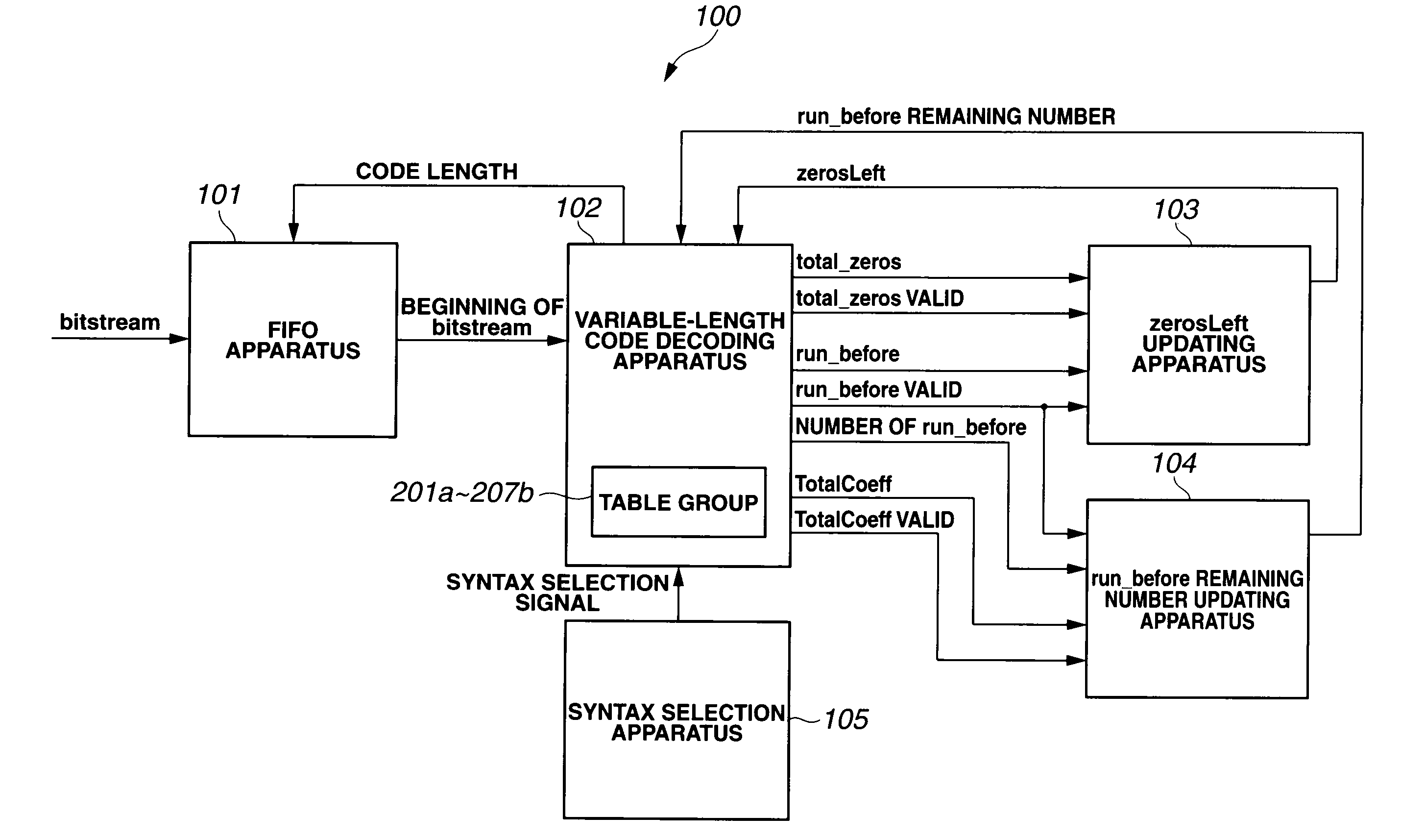
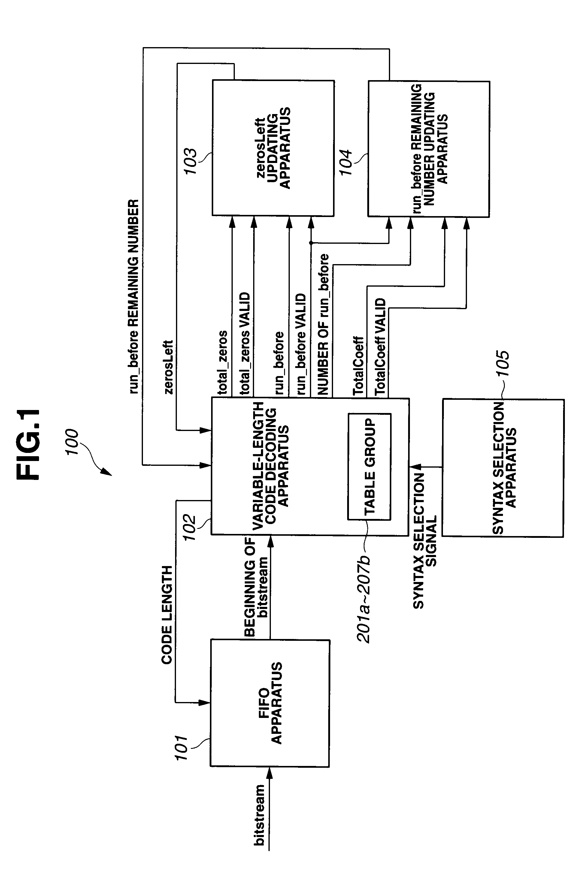
[0045]FIG. 1 is a block diagram of an image decoding apparatus according to a first embodiment of the present invention.

[0046]The image decoding apparatus 100 illustrated in FIG. 1 has the hardware configuration in which run_before syntax is decoded.

[0047]The image decoding apparatus 100 includes: an FIFO apparatus 101 acting as a bitstream updating and output unit configured to receive a bitstream constituted of multiple variable-length code syntaxes, and updates a syntax located at the beginning of the bitstream according to the code length thereof and output the updated syntax; a variable-length code decoding apparatus 102 acting as a bitstream decoding unit configured to decode the variable-length code of the syntax received from the FIFO apparatus 101 in response to a decode request; a zerosLeft updating apparatus 103 configured to update zerosLeft using as an initial value, a specific syntax (for example, total_zeros) decoded by the variable-length code decoding apparatus 102;...


PUM


Abstract

The invention includes: a bitstream updating output unit configured to receive a bitstream and update a syntax element located at a beginning of the bitstream according to a code length thereof and outputs the syntax element; a bitstream decoding unit configured to decode, in response to a decode request, a variable-length code of the syntax element outputted from the bitstream updating output unit; a zerosLeft updating unit configured to update zerosLeft based on a specific syntax element decoded by the bitstream decoding unit; a run_before remaining number updating unit configured to update a run_before remaining number based on a specific syntax element decoded by the bitstream decoding unit; and a syntax selection unit configured to select a syntax element to be decoded by the bitstream decoding unit. Thus, multiple zero run_before syntaxes and one non-zero run_before syntax, or multiple zero run_before syntaxes are decoded all at once.

Description

CROSS REFERENCE TO RELATED APPLICATION[0001]This application is based upon and claims the benefit of priority from the prior Japanese Patent Application No. 2007-63827 filed on Mar. 13, 2007; the entire contents of which are incorporated herein by reference.BACKGROUND OF THE INVENTION[0002]1. Field of the Invention[0003]The present invention relates to an image decoding apparatus and image decoding method configured to decode an image coding bitstream (coded image data) coded in H.264 format.[0004]2. Description of the Related Art[0005]The technique called ITU-T Recommendation H.264 / AVC (Advanced video coding) (simply “H.264” hereafter) defines that DCT coefficients, motion vectors or the like be transmitted using syntaxes indicating the rules of setting coded data streams (bitstreams).[0006]For example, in compressing and coding moving image data and transmitting the resultant data, motion prediction errors (residual blocks) between input data of luminance or color difference and m...

Claims


Application Information

Patent Timeline
IPC IPC(8): H04N7/12H03M7/40H04N19/00H04N19/13H04N19/134H04N19/189H04N19/423H04N19/44H04N19/93
CPCH04N19/70H04N19/42H04N19/44
Inventor SUZUMURA, TATSUHIROOGAWA, TAKAYAOUE, AKIHIRO
Owner KK TOSHIBA
Learn More