Stent for implant guide and prosthetics

a technology for prosthetics and implants, applied in the field of implants, can solve problems such as human error

Inactive Publication Date: 2008-09-18
3M INNOVATIVE PROPERTIES CO
View PDF11 Cites 26 Cited by
  • Summary
  • Abstract
  • Description
  • Claims
  • Application Information

AI Technical Summary

Problems solved by technology

According to Klein, all these previous methods suffer from the drawbacks that the hole(s) in the plastic replica are ultimately drilled by hand by the dentist and this introduces the element of human error.
Problems with Klein's approach include the fact that it is complicated and, also, the fact that it requires the dentist to make a plastic replica of the teeth to be replaced before his inventive procedure is begun.

Method used


Image

  • Stent for implant guide and prosthetics
  • Stent for implant guide and prosthetics
  • Stent for implant guide and prosthetics

Examples


Embodiment Construction

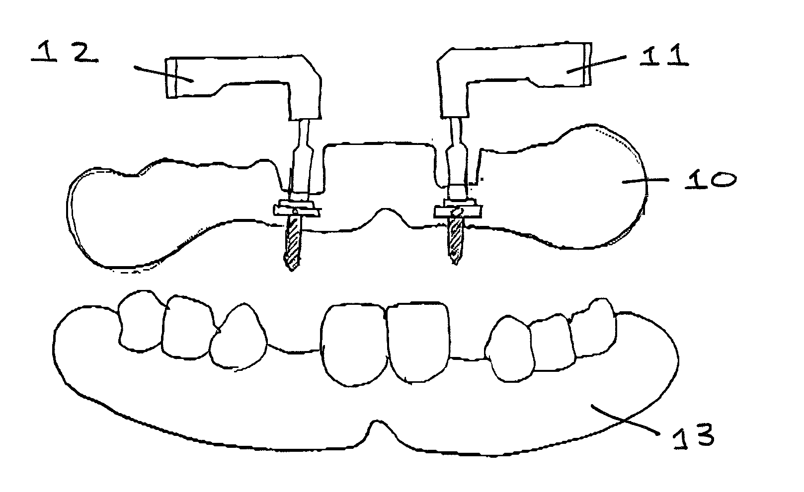
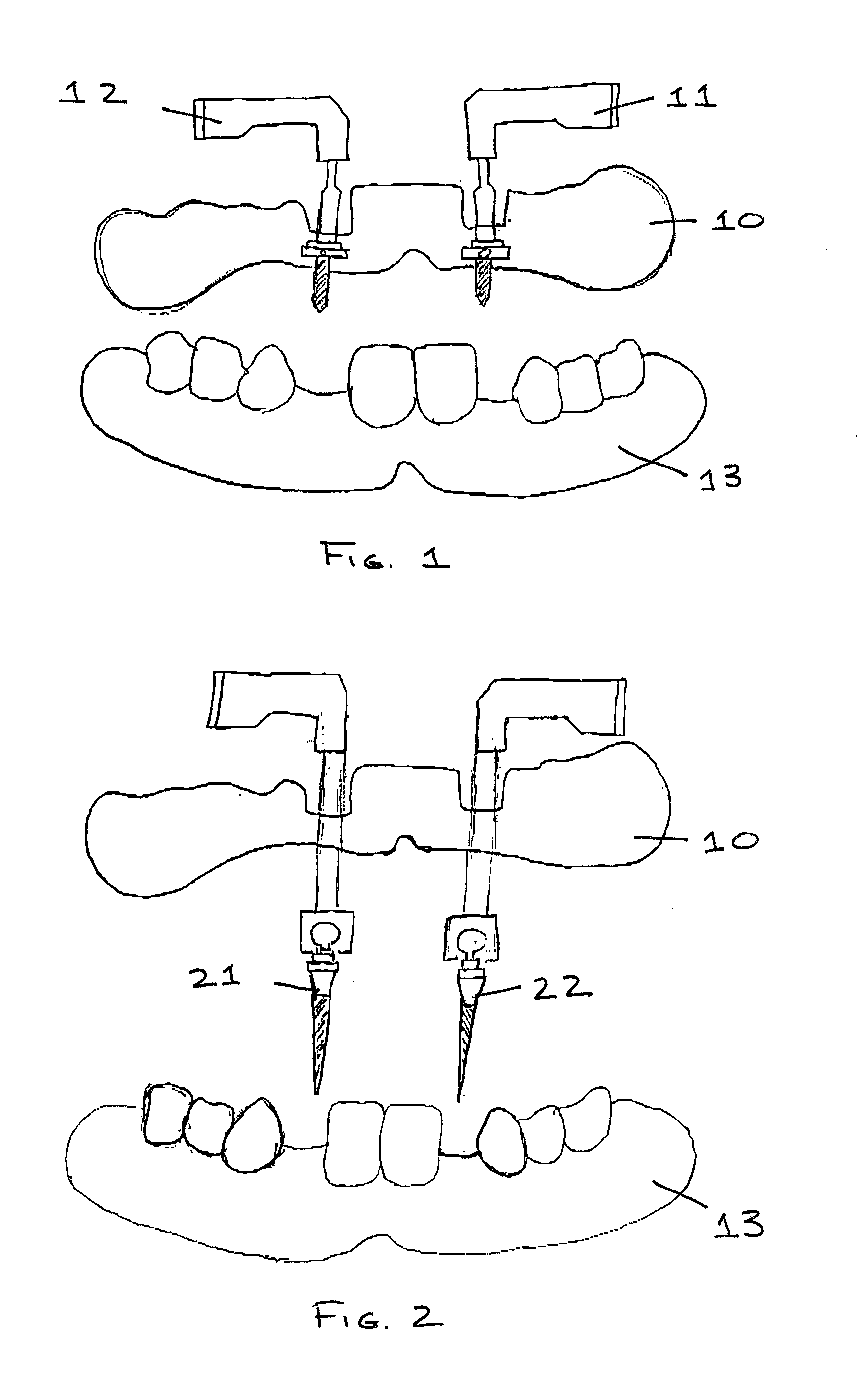
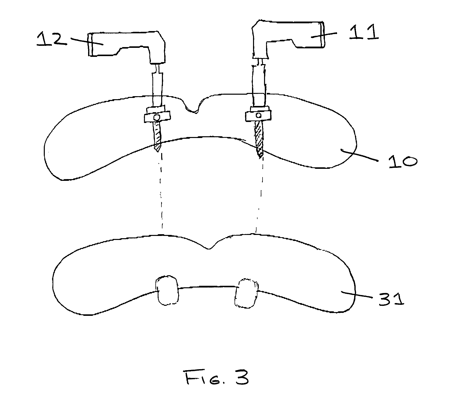
[0041]According to the present invention, scan data from a patient's mouth and a prosthesis or impression is used to construct a virtual model of a dental stent for placing one or more dental implants into the patient's jawbone. That virtual model is then converted to a usable 3-dimensional dental stent. The 3-dimensional dental stent is then used as a guide to place the dental implant(s) into the patient's jawbone with a high degree of accuracy as to the positioning of the implants into the patient's jawbone and with the correct angulation.

[0042]In one embodiment, the virtual model of the dental step is made using a prosthesis.

[0043]In another embodiment, the prosthesis is a denture. The denture may be, for example, a newly created denture. Alternatively, the denture may be a preexisting denture intended to be reseated in the patient's jawbone.

[0044]In another embodiment, the virtual model of the dental step is made using an impression of at least a portion of the patient's upper o...


PUM


Abstract

A method of virtually producing a dental stent for placing one or more dental implants based on data derived from scanning a patient's mouth and a prosthesis to be installed or an impression of the patient's existing teeth. The virtual dental stent is converted to a usable dental stent, which is, thereafter, used to guide the placement of the one or more dental implants into the patient's jawbone. After the dental implants have been placed, a prosthesis can be mounted onto the dental implants.

Description

CROSS-REFERENCE TO RELATED APPLICATION[0001]This application claims priority pursuant to 35 U.S.C. §119(e) of U.S. Provisional Application No. 60 / 906,405, filed on Mar. 12, 2007.BACKGROUND OF THE INVENTION[0002]1. Field of the Invention[0003]The present invention relates to a stent for guiding the installation of dental implants and the seating of prosthetics on the installed implants.[0004]2. Description of Related Art[0005]U.S. Pat. No. 5,967,777 (hereinafter “Klein”) discusses in the Background section thereof various problems encountered previously in installing implants and thereafter proposes a possible solution thereto. Typically, a dentist uses a handheld drill to make a hole in the patient's jawbone at the site that is to receive the dental implant. That hole needs to have a defined trajectory, depth and diameter. These parameters, in turn, depend upon the anticipated position of the patient's teeth to be replaced and supported by the dental implant(s) and, also, the existi...

Claims


Application Information

Patent Timeline
Patent Type & Authority Applications(United States)
IPC IPC(8): A61C8/00A61C13/12
CPCA61C1/084
Inventor BULARD, RONALD A.
Owner 3M INNOVATIVE PROPERTIES CO
Why Eureka
Try Eureka