Decorative Mask

a mask and decorative technology, applied in the field of masks, can solve the problems that the decorative mask b>100/b> will be easily damaged

Inactive Publication Date: 2008-09-25
YEH CHIA CHING +1
View PDF13 Cites 9 Cited by
  • Summary
  • Abstract
  • Description
  • Claims
  • Application Information

AI Technical Summary

Benefits of technology

[0005]To make it easy for our examiner to understand the present invention, the following drawing and numerals will be used for a detail description of the present invention.

Problems solved by technology

If the user wears this decorative mask 100 for many times, the elastic band 120 will become elastically fatigue, and thus the decorative mask 100 will be damaged easily.

Method used


Image

  • Decorative Mask
  • Decorative Mask
  • Decorative Mask

Examples


Embodiment Construction

[0017]The structure and its connecting relation of the present invention will now be described in more detail hereinafter with reference to the accompanying drawings that show various embodiments of the invention as follows.

[0018]Referring to FIG. 3A for an exploded view of a decorative mask in accordance with a first preferred embodiment of the present invention,

[0019]Referring to FIGS. 3A and 3B for an exploded view of a decorative mask and a schematic view of a user wearing the decoratively in accordance with a first preferred embodiment of the present invention respectively, the decorative mask 300 comprises a mask 310 and a head-mounted member 320. When a user 60 wears the decorative mask 300, the head-mounted member 320 is worn on the head 62 of the user 60, so that the mask 310 covers the face 64 of the user 60. The mask 310 includes two first fasteners 312 disposed on an inner lateral side S3 of the mask 310, and the head-mounted member includes two second fasteners 322 corr...


PUM


Abstract

The present invention discloses a decorative mask including a mask and a head-mounted member. The mask applicable for covering the face of a user has two first fasteners installed on an inner lateral side of the mask. The head-mounted member applicable to be worn at the head of the user has two second fasteners corresponding to the first fasteners, and the second fasteners are applicable for engaging or disengaging the first fasteners.

Description

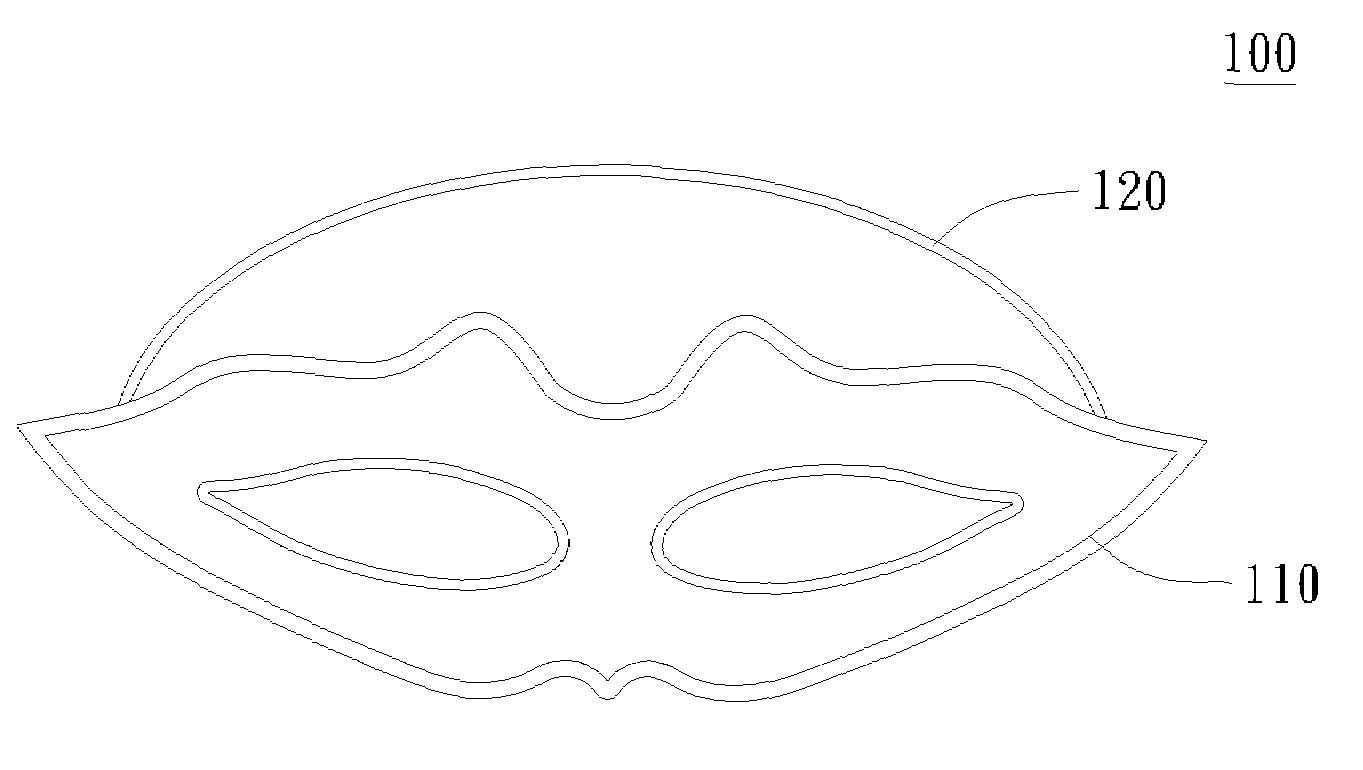
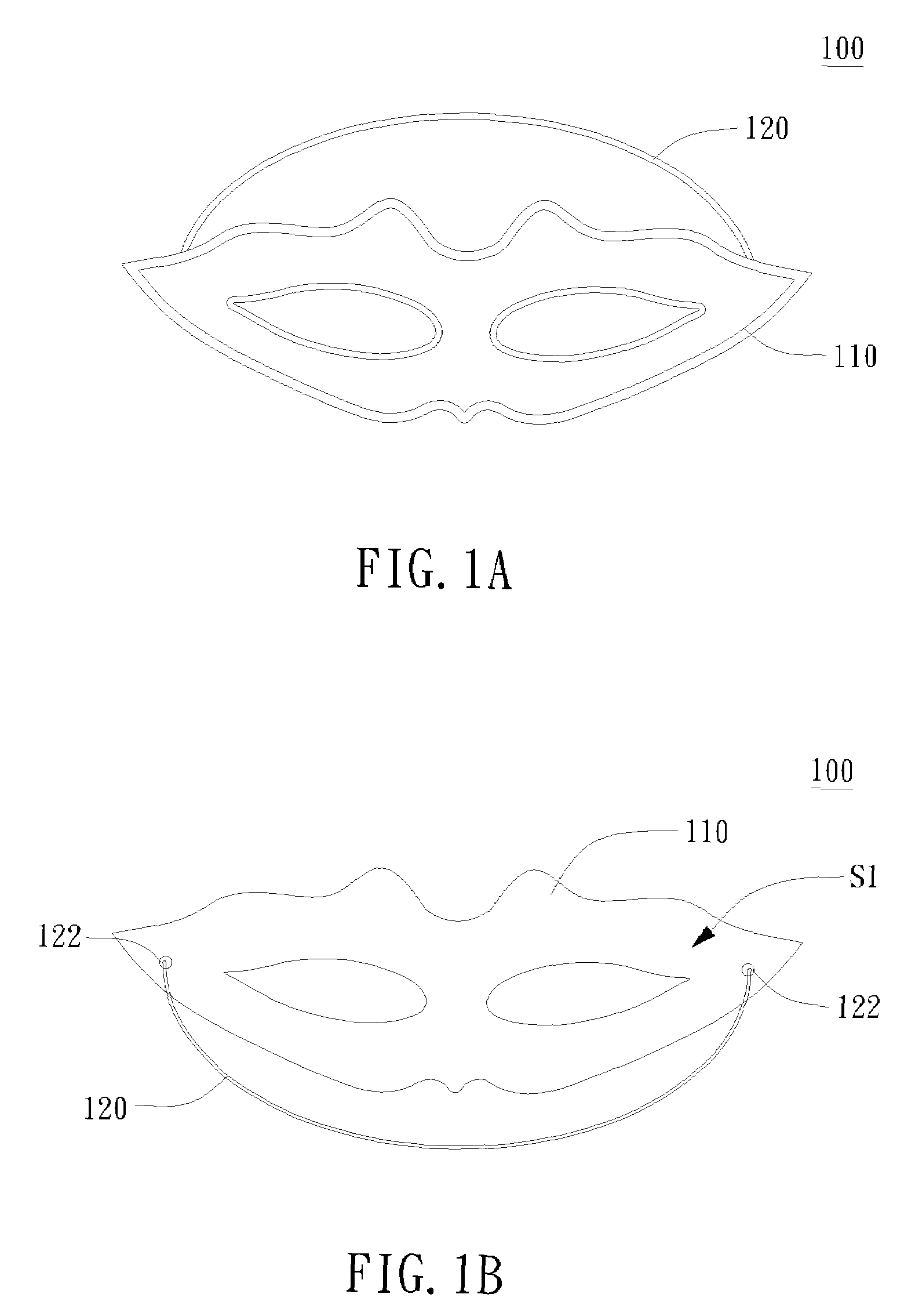
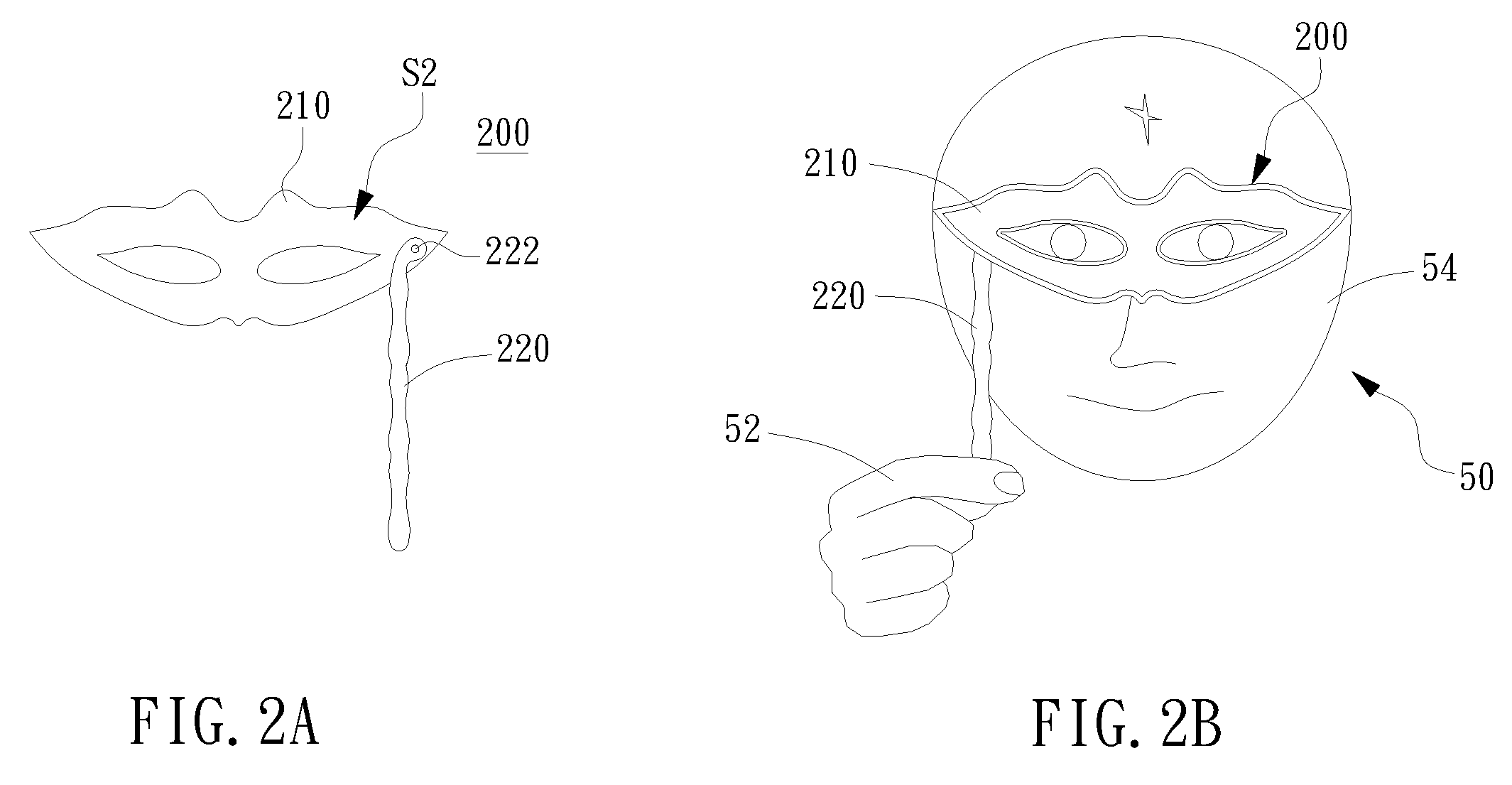
FIELD OF THE INVENTION[0001]The present invention relates to a mask, and more particularly to a decorative mask.BACKGROUND OF THE INVENTION[0002]Referring to FIGS. 1A and 1B for perspective views of a conventional decorative mask viewed at different angles, the decorative mask 100 includes a plastic mask 110 and an elastic band 120, wherein two end points 122 of the elastic band 120 are fixed at an inner lateral side S1 of the plastic mask 110 S1, and a user can slip the elastic band 120 around the user's head to wear the decorative mask 100. If the user wears this decorative mask 100 for many times, the elastic band 120 will become elastically fatigue, and thus the decorative mask 100 will be damaged easily. Since the elastic band 120 is fixed onto the plastic mask 110 and cannot be removed or replaced easily, therefore, users hardly find a way to repair a damaged decorative mask 100.[0003]Referring to FIGS. 2A and 2B for a perspective view of another type of conventional decorativ...

Claims


Application Information

Patent Timeline
Patent Type & Authority Applications(United States)
IPC IPC(8): A42B1/00
CPCA41G7/00
Inventor YEH, CHIA-CHINGYEH, MAO-SHAN
Owner YEH CHIA CHING
Why Eureka
Try Eureka