
Seamless lighting assembly

a technology of lighting assembly and diode, which is applied in the field of lighting, can solve the problems of environmental or safety hazards, inconvenient maintenance, and brittleness of incandescent bulbs, and achieve the effect of improving thermal dissipation capability and increasing efficiency

Inactive Publication Date: 2008-09-25
LED FOLIO CORP
View PDF8 Cites 88 Cited by
  • Summary
  • Abstract
  • Description
  • Claims
  • Application Information

AI Technical Summary

Benefits of technology

[0008]An object of the present invention is to provide a light-emitting diode lighting assembly with a seamless appearance.
[0009]Another object of the present invention is to provide a light-emitting diode lighting assembly with increased efficiency.
[0010]Another object of the present invention is to provide a light-emitting diode lighting assembly with improved thermal dissipation capability.

Problems solved by technology

Such lighting fixtures can be bulky and are generally not energy efficient.
While bulbs usually provide adequate luminous intensity for the lighting of interior spaces, bulbs can often cause problems.
For example, incandescent bulbs are brittle and need frequent replacement.
Fluorescent bulbs are more robust and energy efficient, but often emit light that is less pleasing and cause environmental or safety problems when broken.
However, the positioning of the light-emitting diodes for heat dissipation in an LED lighting fixture may not be conducive to efficient use of the light emanating from the light-emitting diodes.
Further, the addition of heatsink structures for efficient thermal dissipation may detract from the aesthetics of the fixture and impede implementation of the fixture.
The two major design difficulties associated with light emitting diode based ceiling lighting fixtures involve dealing with heat dissipation from the light emitting diodes and increasing brightness / efficiency.
In other words, increasing light emitting diode density in the device increases brightness, but also increases problems associated with light emitting diode overheating.

Method used


Image

  • Seamless lighting assembly
  • Seamless lighting assembly
  • Seamless lighting assembly

Examples


Embodiment Construction

[0029]Reference will now be made in detail to the preferred embodiments of the present invention, examples of which are illustrated in the accompanying drawings. The invention may, however, be embodied in many different forms and should not be construed as being limited to the embodiments set forth herein; rather, these embodiments are provided so that this disclosure will be thorough and complete, and will fully convey the concept of the invention to those skilled in the art. In the drawings, the thicknesses of layers and regions are exaggerated for clarity. Like reference numerals in the drawings denote like elements.

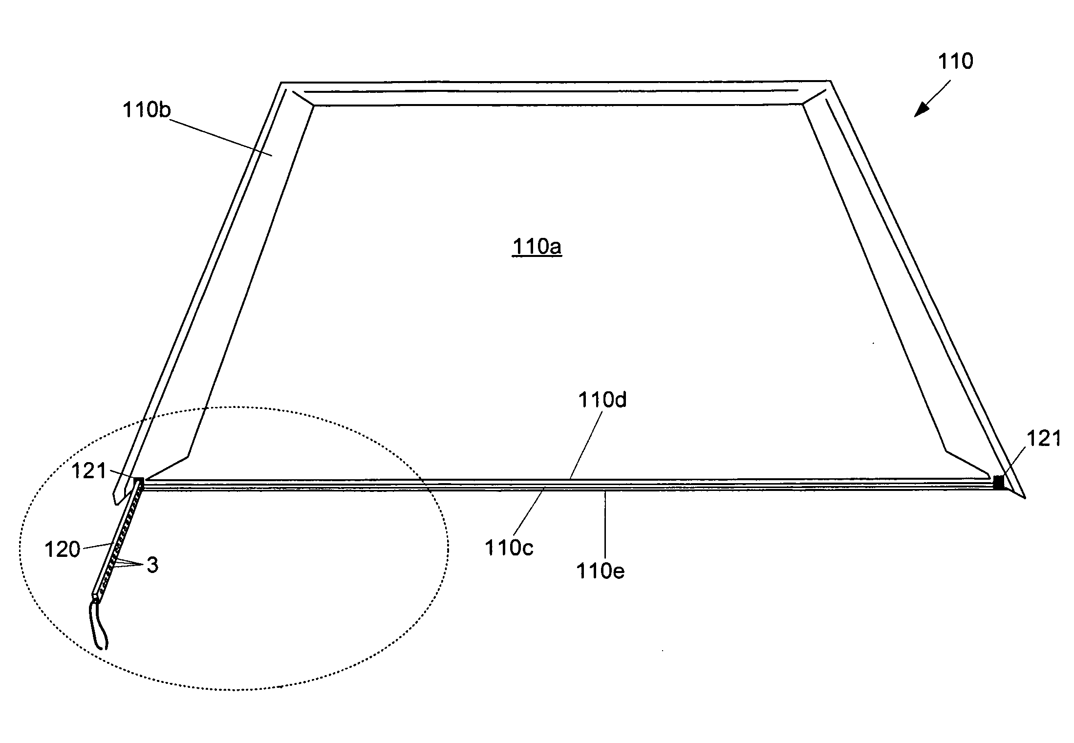
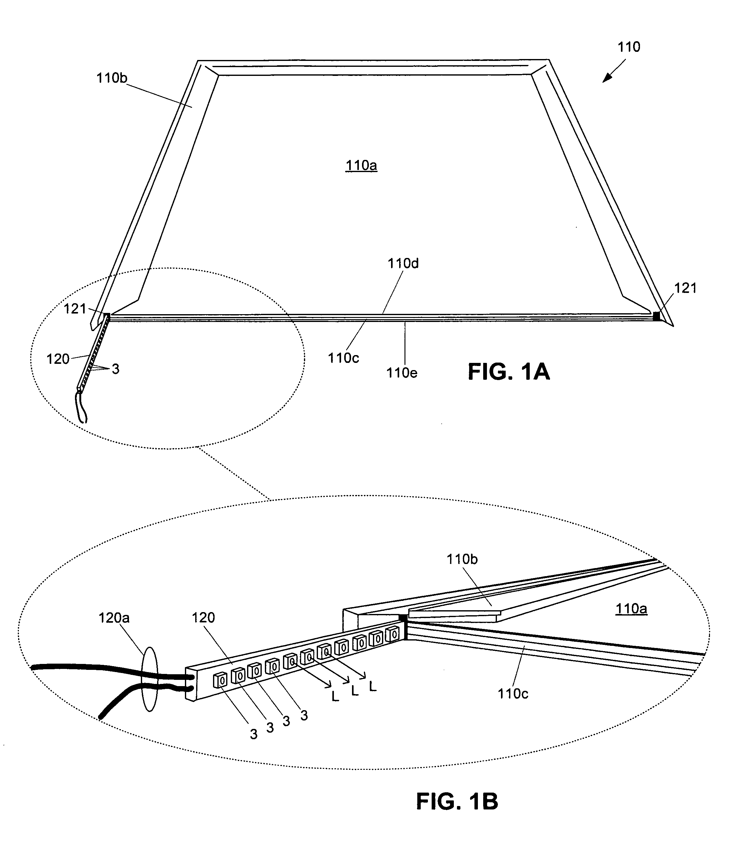
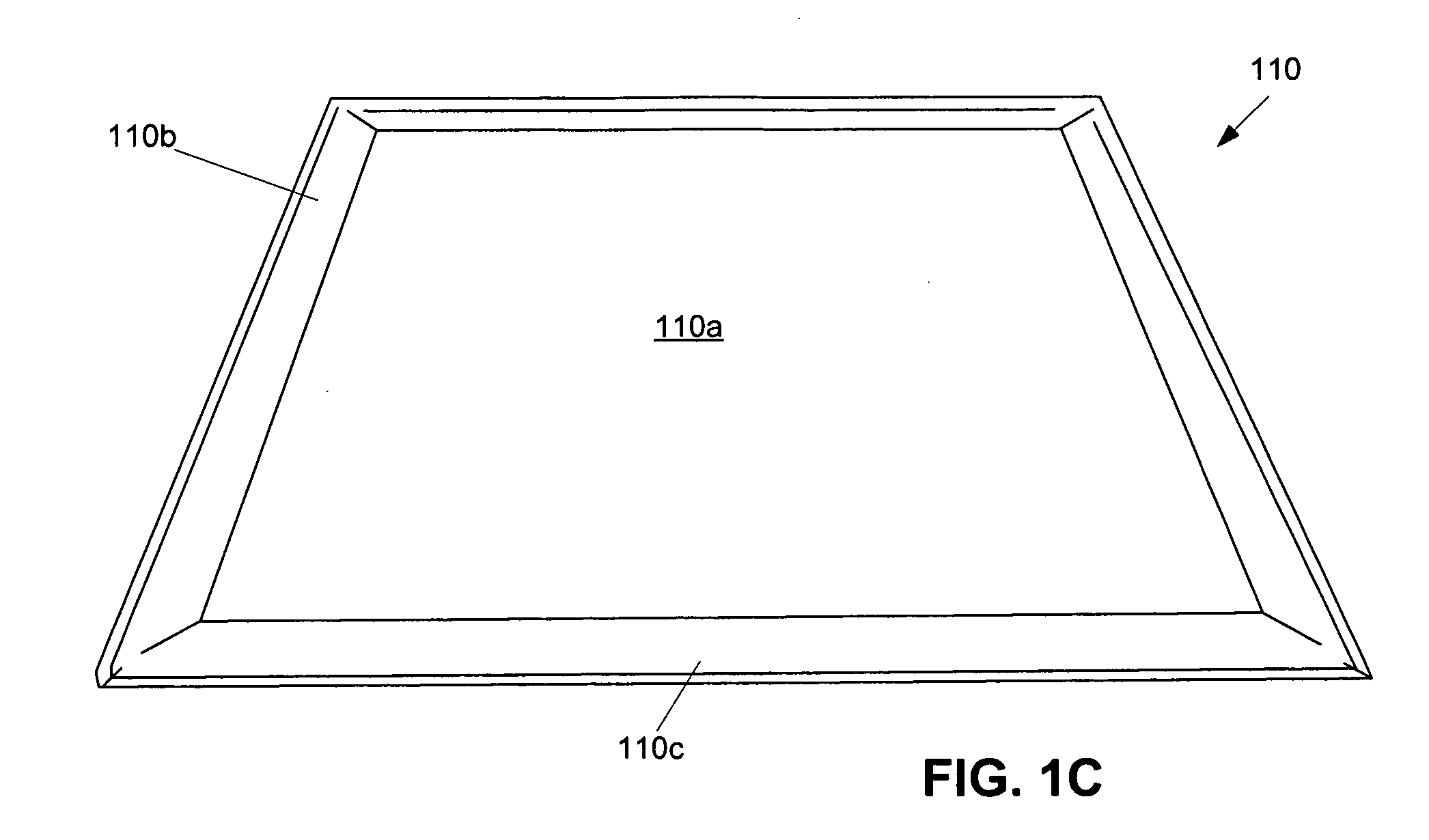
[0030]FIG. 1A is a disassembled view of a light emitting diode panel and FIG. 1B is a close-up perspective view of the light emitting diodes of the light emitting diode panel in FIG. 1A. FIG. 1C is an assembled view of the light emitting diode panel of FIGS. 1A and 1B. As shown in FIG. 1A, each light emitting diode panel 110 a middle section 110a. The periphery of the...


PUM


Abstract

A light-emitting diode lighting assembly, including a plurality of light-emitting diode lighting panels with light-emitting diodes positioned on at least one edge of the light-emitting diode lighting panels, a plurality of prism plates for refracting light emitted by the light-emitting diodes, wherein each of the plurality of prism plates is respectively positioned above one of the light-emitting diode panels, and a top plate covering the plurality of prism plates such that the light emitting diode lighting assembly appears seamless.

Description

[0001]This invention claims the benefit of the Provisional Patent Application 60 / 907,154 filed with the U.S. Patent and Trademark Office on Mar. 22, 2007, which is hereby incorporated by reference in its entirety.BACKGROUND OF THE INVENTION[0002]The present invention relates to lighting, and more particularly, to light-emitting diode lighting assembly. Although the present invention is suitable for a wide scope of applications, it is particularly suitable for providing a seamless light-emitting diode lighting assembly for either drop-ceilings, drywall / plaster ceilings or walls.[0003]In general, ceiling lighting fixtures are either based on incandescent or fluorescent bulbs. Such lighting fixtures can be bulky and are generally not energy efficient. While bulbs usually provide adequate luminous intensity for the lighting of interior spaces, bulbs can often cause problems. For example, incandescent bulbs are brittle and need frequent replacement. Fluorescent bulbs are more robust and ...

Claims


Application Information

Patent Timeline
IPC IPC(8): F21S8/00
CPCE04B9/32F21V29/89F21S8/04F21V5/002F21V5/02F21V15/01F21V27/00F21V29/004F21Y2101/02F21Y2103/003F21Y2105/00G02B6/0053G02B6/0068G02B6/0073G02B6/0088F21V29/74F21S2/00F21Y2103/10F21Y2115/10
Inventor KIM, STEVEN
Owner LED FOLIO CORP
Features
  • Generate Ideas
  • Intellectual Property
  • Life Sciences
  • Materials
  • Tech Scout
  • Unparalleled Data Quality
  • Higher Quality Content
  • 60% Fewer Hallucinations
Learn More