
Method and apparatus for image encoding and image decoding

Inactive Publication Date: 2008-09-25
SAMSUNG ELECTRONICS CO LTD
View PDF6 Cites 52 Cited by
  • Summary
  • Abstract
  • Description
  • Claims
  • Application Information

AI Technical Summary

Benefits of technology

[0010]Aspects of the present invention provide a method and apparatus for image encoding which improves prediction efficiency and compression efficiency when an image is encoded, and a method and apparatus for image decoding.

Problems solved by technology

However, pixels of the current image block, which are disposed far from the pixels of the previous blocks, may have large differences between prediction values and original pixel values.
In the two-dimensional DCT, although horizontal or vertical correlations exist in the residual data, the correlations between data in a residual block may not be efficiently used.

Method used


Image

  • Method and apparatus for image encoding and image decoding
  • Method and apparatus for image encoding and image decoding
  • Method and apparatus for image encoding and image decoding

Examples


Embodiment Construction

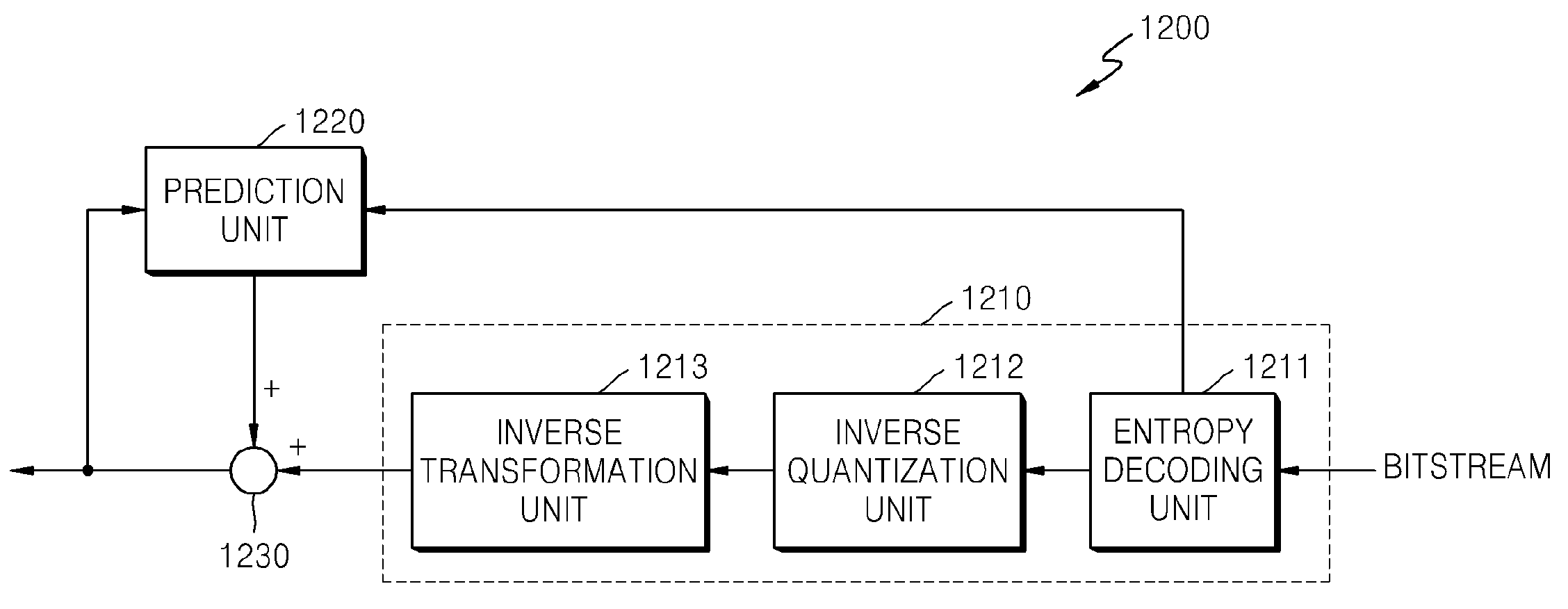
[0033]Hereinafter, the present invention will be described in detail by explaining exemplary embodiments of the invention with reference to the attached drawings.

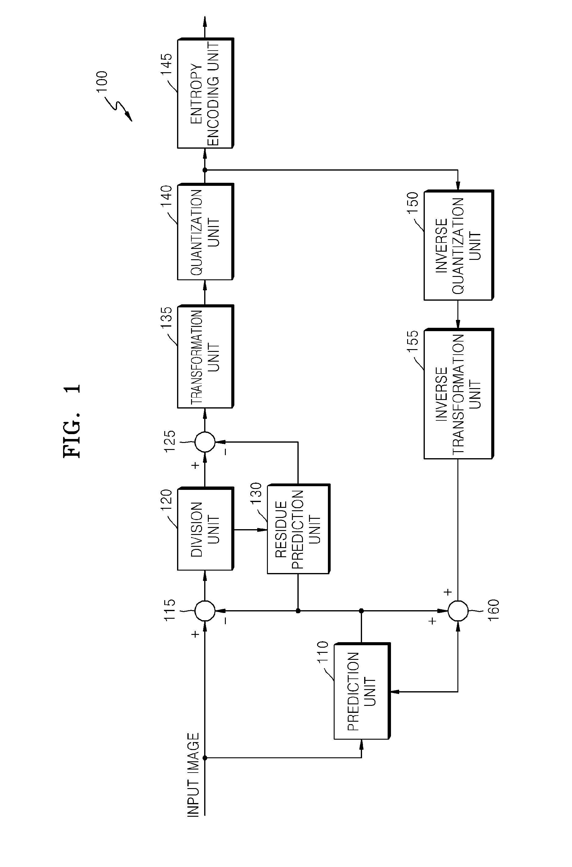
[0034]FIG. 1 is a block diagram illustrating an apparatus 100 for image encoding, according to an exemplary embodiment of the present invention.

[0035]The apparatus 100 divides a residual block, that is, a difference between an original image block and a prediction image block into a plurality of sub residual blocks, generates prediction sub residual blocks of the sub residual blocks by using neighboring residues, and transforms difference sub residual blocks that are differences between the original sub residual blocks and the prediction sub residual blocks.

[0036]Referring to FIG. 1, the apparatus 100 includes a prediction unit 110, a first subtraction unit 115, a division unit 120, a second subtraction unit 125, a residue prediction unit 130, a transformation unit 135, a quantization unit 140, an entropy encoding unit 145,...


PUM


Abstract

Provided are a method and apparatus for image encoding which improves encoding efficiency in accordance with image characteristics by performing prediction in lines and performing a one-dimensional transformation in lines on an input image, and a method and apparatus for image decoding. Encoding efficiency of an image may be improved by generating a prediction sub residual block using neighboring residues and performing a one-dimensional discrete cosine transformation (DCT) on a difference residual block which is a difference between an original sub residual block and the prediction sub residual block.

Description

CROSS-REFERENCE TO RELATED PATENT APPLICATION[0001]This application claims priority from Korean Patent Application No. 10-2007-0028886, filed on Mar. 23, 2007, in the Korean Intellectual Property Office, the disclosure of which is incorporated herein in its entirety by reference.BACKGROUND OF THE INVENTION[0002]1. Field of the Invention[0003]Apparatuses and methods consistent with the present invention relate to image encoding and image decoding, and more particularly, to image encoding which improves prediction efficiency and compression efficiency in accordance with image characteristics by performing prediction in lines and performing a one-dimensional transformation in lines on an input image.[0004]2. Description of the Related Art[0005]In general, according to video compression standards such as Moving Picture Experts Group (MPEG)-1, MPEG-2, MPEG-4 Visual, H.261, H.263 and H.264, image data is compressed by dividing an image frame into a plurality of image blocks, performing pr...

Claims


Application Information

Patent Timeline
IPC IPC(8): G06K9/46H04N19/593
CPCH04N19/00569H04N19/105H04N19/50H04N19/176H04N19/147H04N19/523H04N19/169H04N19/61H04N19/593H04N19/11H04N19/109H04N19/122H04N19/60
Inventor SOHN, YU-MIHAN, WOO-JIN
Owner SAMSUNG ELECTRONICS CO LTD
Learn More