Uplink control channel allocation

Active Publication Date: 2008-09-25
APPLE INC
View PDF10 Cites 161 Cited by
  • Summary
  • Abstract
  • Description
  • Claims
  • Application Information

AI Technical Summary

Problems solved by technology

System overhead as it grows chips away at system capacity and thus is at odds with the objective of maximizing service availability.

Method used


Image

  • Uplink control channel allocation
  • Uplink control channel allocation
  • Uplink control channel allocation

Examples


Embodiment Construction

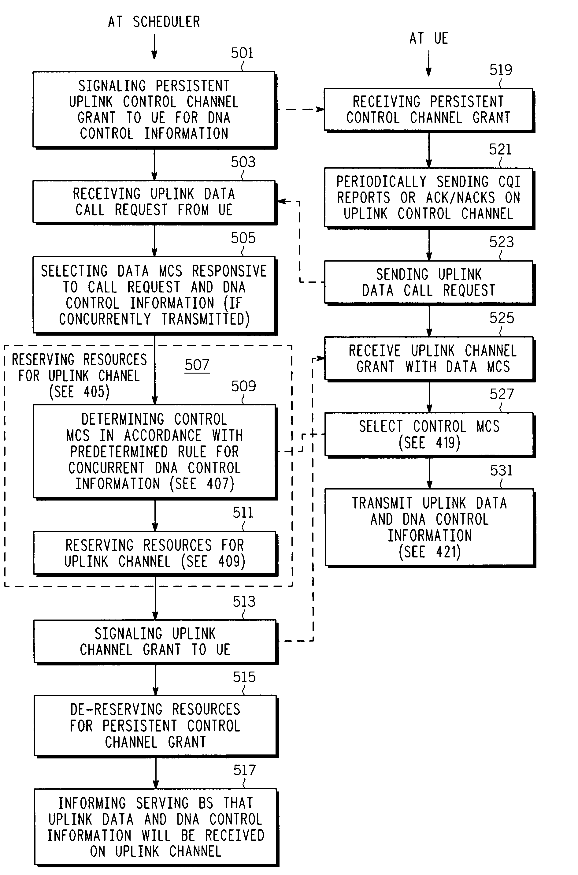
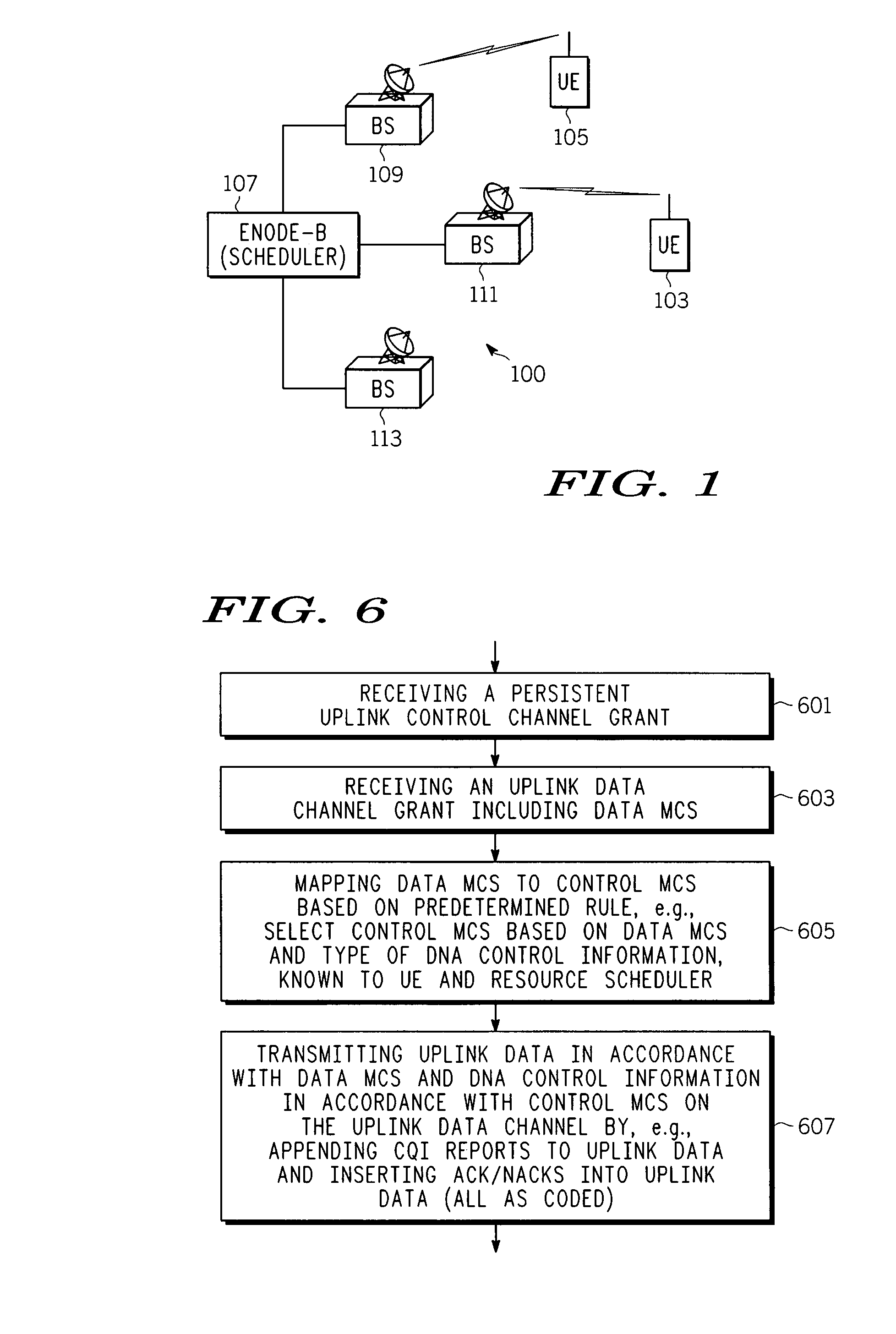
[0012]In overview, the present disclosure concerns communication systems and equipment, e.g., resource schedulers and user equipment (UE), and more specifically techniques and approaches for allocation or configuration of uplink control channels. More particularly various inventive concepts and principles embodied in methods and apparatus, which are arranged to reduce or eliminate overhead associated with setting up or providing a grant for such control channels will be discussed and disclosed.

[0013]The communication systems, resource schedulers, UEs and methods therein of particular interest may vary widely but include such apparatus and methods suitable for utilization in systems using air interfaces being proposed and developed, such as the Evolved—Universal Terrestrial Radio Access (E-UTRA) standards within the long term evolution (LTE) system work under the auspices of the third generation partnership project (3GPP). These air interface standards are defined or organized such t...


PUM


Abstract

Various methods of allocating uplink control channels in a communication system are implemented at a resource scheduler or a user equipment (UE). In one method the scheduler reserves resources for a downlink data channel and signals a corresponding downlink data channel grant and also reserves resources for a persistent uplink control channel for a longer duration than the data channel grant. Signaling overhead associated with a grant for this persistent uplink control channel is reduced over a full dynamic grant. A predetermined rule can be used at the scheduler and at the UE to avoid overhead signaling associated with a grant for this persistent control channel. Predetermined rules at the UE and scheduler can also be used to reserve appropriate resources and select appropriate MCS levels for control information and the control information and uplink data can be transported over a common uplink channel when a time overlap occurs between an uplink data channel and the persistent control channel.

Description

FIELD OF THE INVENTION[0001]This invention relates in general to communication systems and equipment and more specifically to techniques and apparatus for allocating resources for communication channels.BACKGROUND OF THE INVENTION[0002]Communications systems and equipment are known and continue to evolve. Many of these systems now have uplink data channels and downlink data channels as well as uplink and downlink control channels. Many of these channels are further distinguished in varying manners. Generally the control channels are used to establish control parameters for the systems and equipment and in the allocation of communication resources among user equipment (UE). The control schemes also consider battery life for UEs and thus are designed to limit the time and extent that each UE is operational.[0003]In an effort to provide as many services to as many users on an as needed basis as possible given a finite resource (spectrum allocation), proposed systems carefully control U...

Claims


Application Information

Patent Timeline
Patent Type & Authority Applications(United States)
IPC IPC(8): H04Q7/20H04W28/16H04W72/04H04W72/12H04W76/02
CPCH04W72/04H04W72/1263H04W72/0413H04W28/26H04W72/1284H04W72/21H04W72/23H04L1/0003H04L5/0055
Inventor MCCOY, JAMES W.DEHNER, LEO G.KOTECHA, JAYESH H.MUNDARATH, JAYAKRISHNAN C.
Owner APPLE INC
Why Eureka
Try Eureka