Non-Disruptive Activity Switching on Remote Control

a technology of non-disruptive activity and remote control, which is applied in the direction of selective content distribution, television systems, instruments, etc., can solve the problems of not being able to consult the epg while continuing to play out a dvd in this context, and may have an undesired or unintended effect of switching

Inactive Publication Date: 2008-09-25
KONINKLIJKE PHILIPS ELECTRONICS NV
View PDF14 Cites 12 Cited by
  • Summary
  • Abstract
  • Description
  • Claims
  • Application Information

AI Technical Summary

Benefits of technology

[0005]One of the objects of the invention is to render task-oriented or activity-oriented control user-friendlier and less prone to give rise to undesired or unintended consequences.

Problems solved by technology

The inventors have realized that this switching may have an undesired or unintended effect under some circumstances.
In other words, consulting the EPG while continuing to play out a DVD is not possible in this context.

Method used


Image

  • Non-Disruptive Activity Switching on Remote Control
  • Non-Disruptive Activity Switching on Remote Control
  • Non-Disruptive Activity Switching on Remote Control

Examples


Embodiment Construction

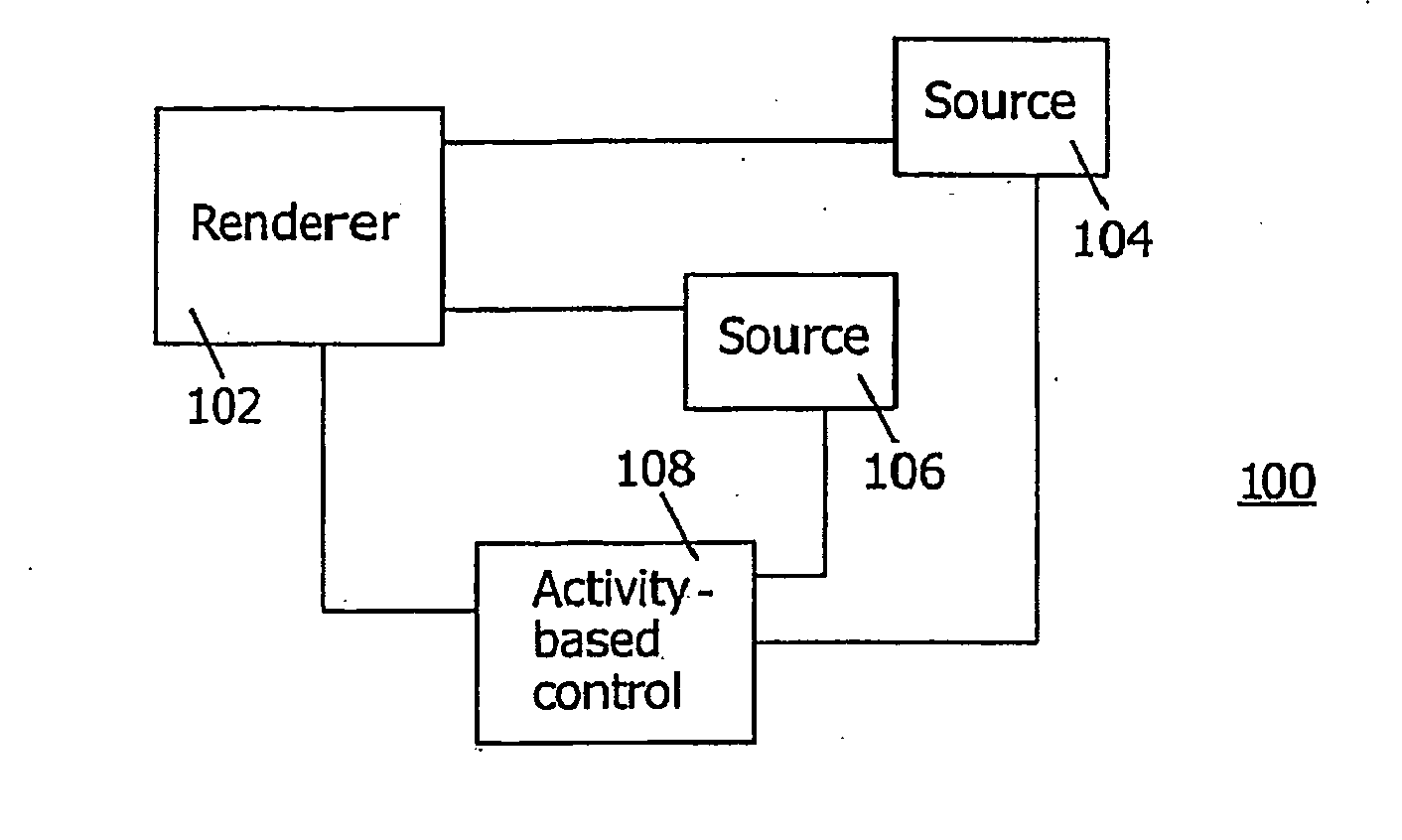
[0013]The invention relates to the task-based or activity-based control of functionalities on a network, e.g., a home network, that has different sources for supply of content information and different renderers for rendering content. Assume that a particular activity involves a certain source. Performing an operation on another source does not always imply that the user wants to switch to another activity, e.g., switch the currently active renderer to another source and turning off the current source, as illustrated in the examples mentioned above. Accordingly, the inventors propose to build in a way to confirm or validate the switching of activities before carrying it out. These and other aspects are illustrated below.

[0014]FIG. 1 is a block diagram of a system 100 in the invention. System 100 comprises a renderer 102 and sources 104, . . . , 106. Renderer 102 is configured to render content, e.g., audio, video, still pictures, graphics, etc., supplied by sources 104-106. Renderer...


PUM


Abstract

A control device has an activity-based user interface for controlling a system with a renderer and multiple sources. The renderer is configured for rendering content available from the multiple sources. The user interface provides a first set of user controls for control of the system in a first activity, and a second set of further user controls for control of the system in a second activity. The control device controls switching the system from the first activity to the second activity upon detecting a validating user interaction with the user interface to validate the switching.

Description

FIELD OF THE INVENTION[0001]The invention relates to a control device for control of a system with a renderer and multiple sources supplying content to the renderer. The invention also relates to a method of enabling to control such as system and to control software for being installed on a control device.BACKGROUND ART[0002]Conventional remote control devices have user interfaces that are “device oriented”. That is, the user interface of such as remote represents controllable devices with which the user can interact in order to initiate a task such as “Watch TV” or “Watch DVD” or “Listen to the radio”. The user then has to select the various controllable devices involved in the desired task and control their functionalities through the remote. This may require some navigation in the user interface of the remote. For example, the user interface of the remote control device comprises a display monitor with a touch screen that provides access to specific pages of control buttons, each...

Claims


Application Information

Patent Timeline
Patent Type & Authority Applications(United States)
IPC IPC(8): G06F3/048G06F3/0482G08C17/02G08C23/04H03J9/00H04N5/445
CPCG06F3/0482G08C17/02G08C23/04H03J9/00H04N21/482H04N5/44582H04N21/42204H04N21/43615H04N5/44543H04N21/47G06F9/451G06F3/0416
Inventor MUSSCHEBROECK, RUDYTHISSEN, ROGIER LOUIS JACQUES WILLEMPEIFFER, WERNER P.HINTZEN, REINHARD LEONARD
Owner KONINKLIJKE PHILIPS ELECTRONICS NV
Why Eureka
Try Eureka