
Honeycomb structure, method of manufacturing honeycomb structure, exhaust gas treating apparatus, and method of manufacturing exhaust gas treating apparatus

a technology of honeycomb and honeycomb structure, which is applied in the direction of catalyst activation/preparation, machines/engines, metal/metal-oxide/metal-hydroxide catalysts, etc., can solve the problems of forming defects such as holes or scratches on the honeycomb structure, and soot contained in exhaust gas discharged from internal combustion engines of vehicles such as buses and trucks, and causing damage to the environment and humans

Active Publication Date: 2008-10-02
IBIDEN CO LTD
View PDF30 Cites 94 Cited by
  • Summary
  • Abstract
  • Description
  • Claims
  • Application Information

AI Technical Summary

Problems solved by technology

Particulates such as soot contained in exhaust gas discharged from internal combustion engines of vehicles such as buses and trucks, construction machines, and the like, for example, are harmful to the environment as well as humans.
It is noted that defects such as holes or scratches may be formed on the honeycomb structure during the manufacturing process of the honeycomb structure or the manufacturing process of the exhaust gas treating apparatus.

Method used


Image

  • Honeycomb structure, method of manufacturing honeycomb structure, exhaust gas treating apparatus, and method of manufacturing exhaust gas treating apparatus
  • Honeycomb structure, method of manufacturing honeycomb structure, exhaust gas treating apparatus, and method of manufacturing exhaust gas treating apparatus
  • Honeycomb structure, method of manufacturing honeycomb structure, exhaust gas treating apparatus, and method of manufacturing exhaust gas treating apparatus

Examples


example 1

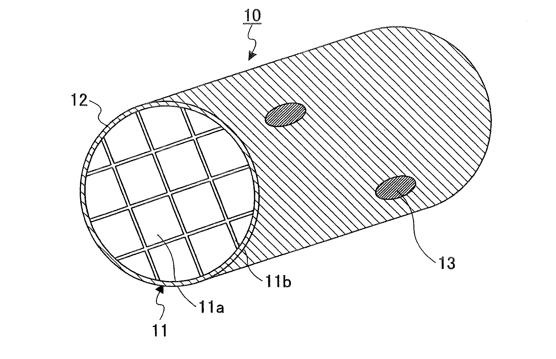
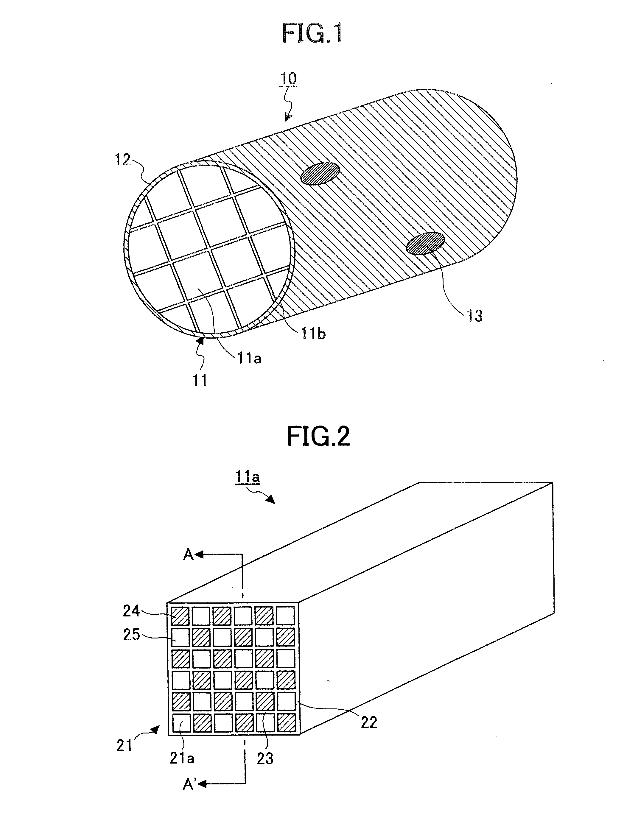
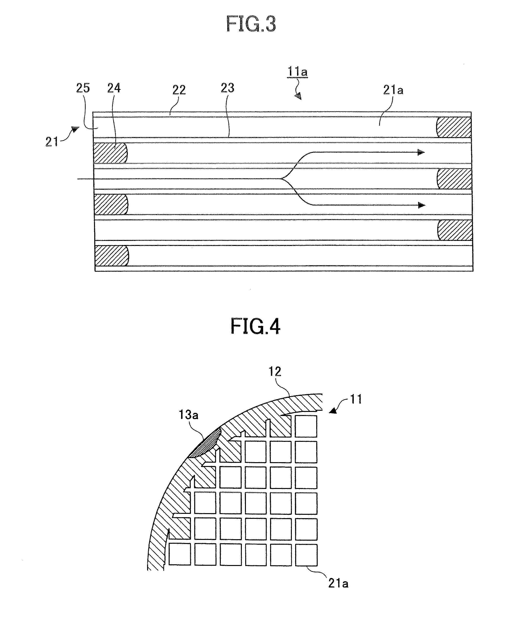
[0091]A defective portion formed on the coating layer 12 of a honeycomb structure fabricated in the above-described manner is filled with a red paste, which is made by adding 1 wt % of iron oxide (Fe2O3) to the coating layer paste. The surface of the defective portion with the red paste is then flattened after which the red paste is dried for 60 minutes at a temperature of 180° C. The honeycomb structure 10 having a defective portion mended in this way to form a mended portion 13 is used in assembling an exhaust gas treating apparatus.

example 2

[0092]A defective portion that is formed on the coating layer 12 of a honeycomb structure carrying the platinum catalyst is filled with a blue paste, which is made by adding 1 wt % of CoO.Al2O3 to the coating layer paste. The surface of the defective portion with the blue paste is then flattened after which the blue paste is dried for 60 minutes at a temperature of 180° C. The honeycomb structure 10 having a defective portion mended in this way to form a mended portion 13 is used in assembling an exhaust gas treating apparatus.

example 3

[0093]A defective portion that is formed on the coating layer 12 of a honeycomb structure that is to be accommodated inside a metal container (shell) is filled with a yellow paste, which is made by adding 1 wt % of ZrO2.V2O5 to the coating layer paste. The surface of the defective portion with the yellow paste is then flattened after which the yellow paste is dried for 60 minutes at a temperature of 180° C. The honeycomb structure 10 having a defective portion mended in this way to form a mended portion 13 is used in assembling an exhaust gas treating apparatus.


PUM

PropertyMeasurementUnit
Temperatureaaaaaaaaaa

Abstract

A honeycomb structure including plural cells with holes arranged in a longitudinal direction, a peripheral wall, and a defective portion formed on the peripheral wall that is mended with a mending material that is in a color different from the color of the peripheral wall. Also, a method is provided for manufacturing a honeycomb structure including plural cells with holes arranged in a longitudinal direction and a peripheral wall which method involves mending a defective portion formed on the peripheral wall of the honeycomb structure with a mending material in a color different from the color of the peripheral wall.

Description

CROSS-REFERENCE TO RELATED APPLICATION[0001]The present application claims priority to PCT Application No. PCT / JP2007 / 056964, filed on Mar. 29, 2007, the entire contents of which are hereby incorporated by reference.BACKGROUND OF THE INVENTION[0002]1. Field of the Invention[0003]The present invention relates to treatment of a gas stream, such as an exhaust gas stream of an internal combustion engine.[0004]2. Discussion of the Background[0005]Particulates such as soot contained in exhaust gas discharged from internal combustion engines of vehicles such as buses and trucks, construction machines, and the like, for example, are harmful to the environment as well as humans. In turn, a variety of exhaust gas treating apparatuses have been developed that use a honeycomb structure made of porous ceramic as a filter for capturing particulates contained in the exhaust gas to purify the exhaust gas. Such an exhaust gas treating apparatus may be manufactured by arranging the surface of the hon...

Claims


Application Information

Patent Timeline
IPC IPC(8): B01D39/20B05D3/02B32B3/12
CPCB01D46/0086Y10T156/10B01D46/2459B01D46/2462B01D2279/30B01J23/42B01J35/04B01J37/0242C04B41/009C04B41/4576C04B41/85C04B2111/00793C04B2111/0081F01N3/2828F01N2450/28F01N2550/00F01N2550/04B01D46/2451Y10T428/24149C04B14/301C04B41/5059C04B41/5089C04B2103/54C04B35/00C04B35/195C04B35/565C04B35/478C04B38/0006B01D46/2478B01J35/56B01D46/2444B01D46/24494
Inventor ITO, TOSHIHIDE
Owner IBIDEN CO LTD
Learn More