Spot welding electrode tip wear verification method

Inactive Publication Date: 2008-10-02
HONDA MOTOR CO LTD
View PDF10 Cites 16 Cited by
  • Summary
  • Abstract
  • Description
  • Claims
  • Application Information

AI Technical Summary

Benefits of technology

[0010]The weld electrode tip wear verification method (tip wear verification method) of the present invention can be used to determine if an individual tip dressing operation, or some selected number of tip dressing oper

Problems solved by technology

Thus, improper tip dres

Method used


Image

  • Spot welding electrode tip wear verification method
  • Spot welding electrode tip wear verification method
  • Spot welding electrode tip wear verification method

Examples


Embodiment Construction

)

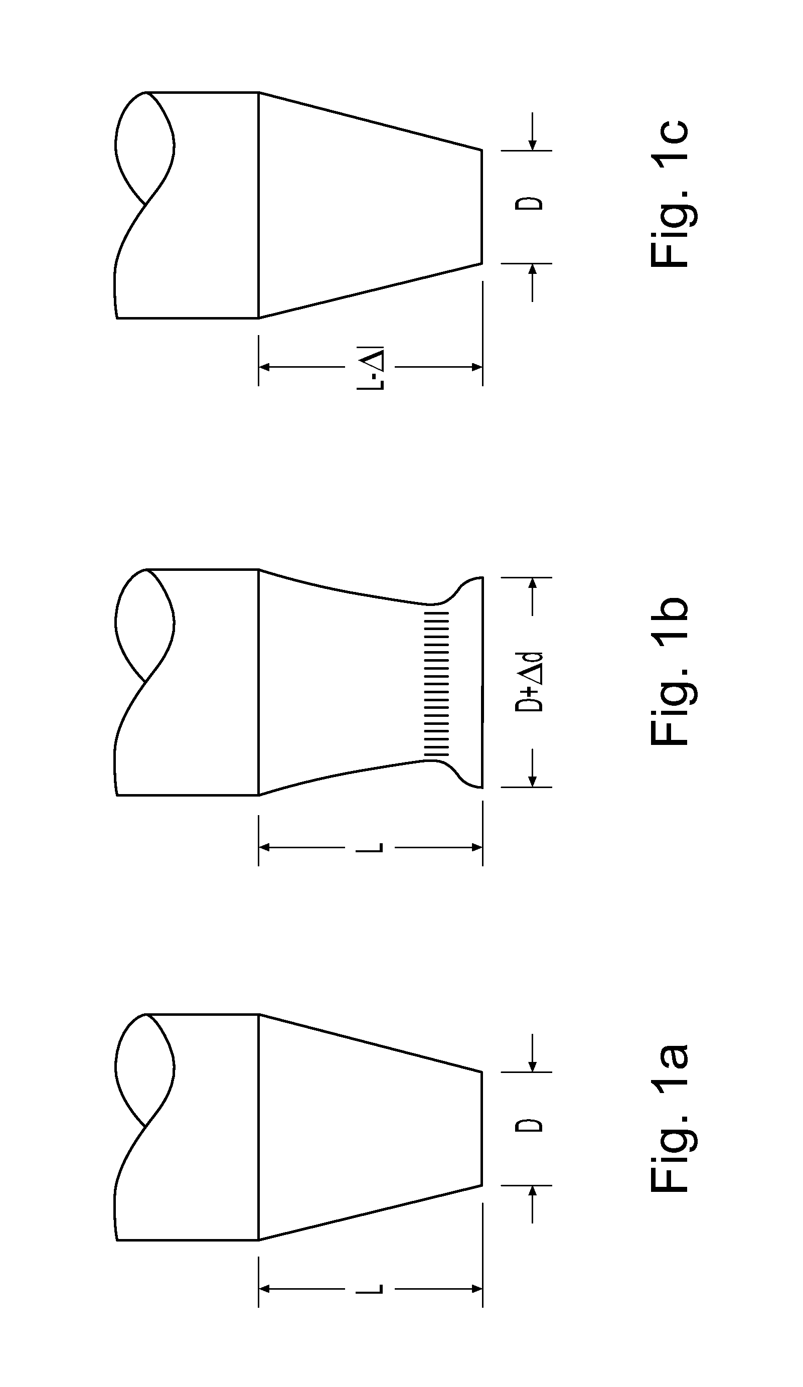
[0019]An exemplary spot weld electrode 5 is illustrated in FIG. 1a. in an unused condition. As shown, a tip portion 10 of the weld electrode 5 is substantially frustoconical in shape, with a length L and a diameter D. The weld electrode 5 would be used in conjunction with a second, corresponding weld electrode, to spot weld sheets of material that would be placed therebetween.

[0020]The spot weld electrode 5 is depicted in a post-welding condition in FIG. 1b. It can be seen that the previously frustoconical shape of the weld electrode 5 has been deformed by the welding process. More specifically, the previous diameter D of the tip face 15 has been increased (to D+Δd) by a mushrooming of the weld electrode 5. Further, the previous length L of the weld electrode 5 may be slightly reduced. As such, the weld electrode 5 must be subjected to a tip dressing operation.

[0021]The weld electrode 5 is shown after tip dressing in FIG. 1c. As can be seen, the tip face 15 has been returned to its...


PUM

PropertyMeasurementUnit
Lengthaaaaaaaaaa

Abstract

A method for ensuring that a spot weld electrode tip dressing operation is performed properly at each occurrence thereof. The method of the present invention takes advantage of an electrode wear compensation routine inherent to most spot weld robots. The method uses measurements of total tip wear as determined by the electrode wear compensation routine to calculate a difference in electrode wear between selected numbers of successive tip dressing operations. This value is then used to perform a comparison with the stored average tip wear per tip dress value, or a tip wear value derive therefrom, to conclude whether the tip dressing operation is operating properly.

Description

BACKGROUND OF THE INVENTIVE FIELD[0001]The present invention is directed to a method for monitoring the wear of a spot weld electrode. More particularly, the present invention is directed to a method for monitoring the amount of wear imparted to a spot weld electrode during a tip dressing operation and for verifying that the tip dressing operation is being properly performed.[0002]Spot welding is a commonly employed resistance welding technique used to join metallic work pieces. Spot welding operates by passing electric current through the work pieces to be joined. This causes a localized heating of the work pieces that is sufficient to produce a molten weld pool therebetween. Upon cooling, the weld pool forms a weld nugget that joins the work pieces.[0003]As it is desirable to conduct the electric current as efficiently as possible, conducting electrodes are employed to contact the work pieces at the welding location. Although various conductive metals may technically be used, copp...

Claims


Application Information

Patent Timeline
IPC IPC(8): B23K11/36B23K11/11
CPCB23K11/3063
Inventor PHILLIPS, WINDHAM
Owner HONDA MOTOR CO LTD
Why Eureka
Try Eureka