
Tag communication device, control method thereof, and control program

Active Publication Date: 2019-10-24
ORMON CORP
View PDF1 Cites 0 Cited by
  • Summary
  • Abstract
  • Description
  • Claims
  • Application Information

AI Technical Summary

Benefits of technology

The patent is about a device that can better locate a specific RFID tag. This can improve the accuracy of operations performed on the tag.

Problems solved by technology

However, in the conventional technology such as that described above, there is a likelihood of the identification of the position of an RFID tag becoming inaccurate due to the influence of multiple paths generated in accordance with reflection of radio waves.
As a result, there is concern of an operation being performed for an RFID tag that is not present at a specific position.

Method used


Image

  • Tag communication device, control method thereof, and control program
  • Tag communication device, control method thereof, and control program
  • Tag communication device, control method thereof, and control program

Examples


application example

§ 1 Application Example

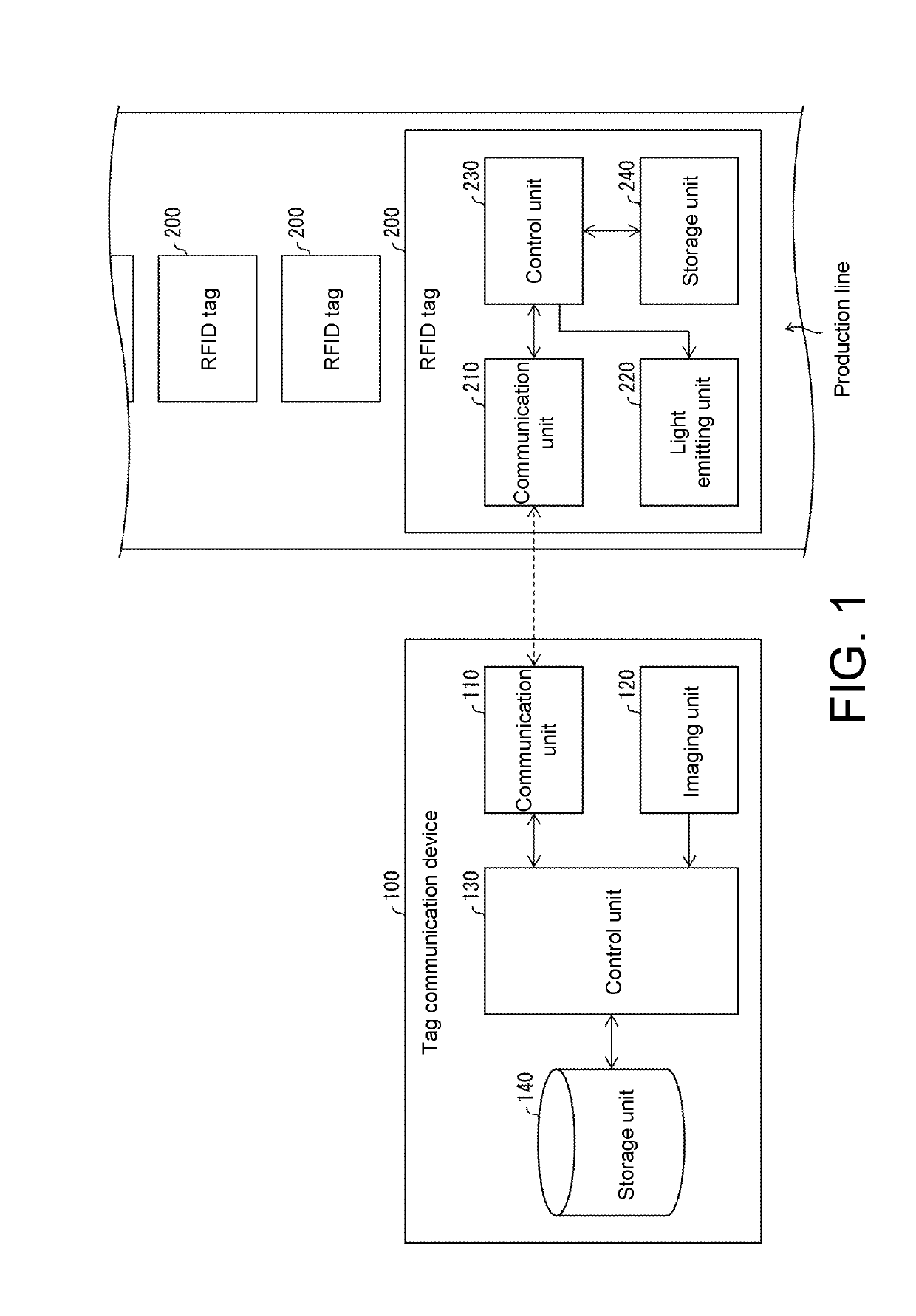
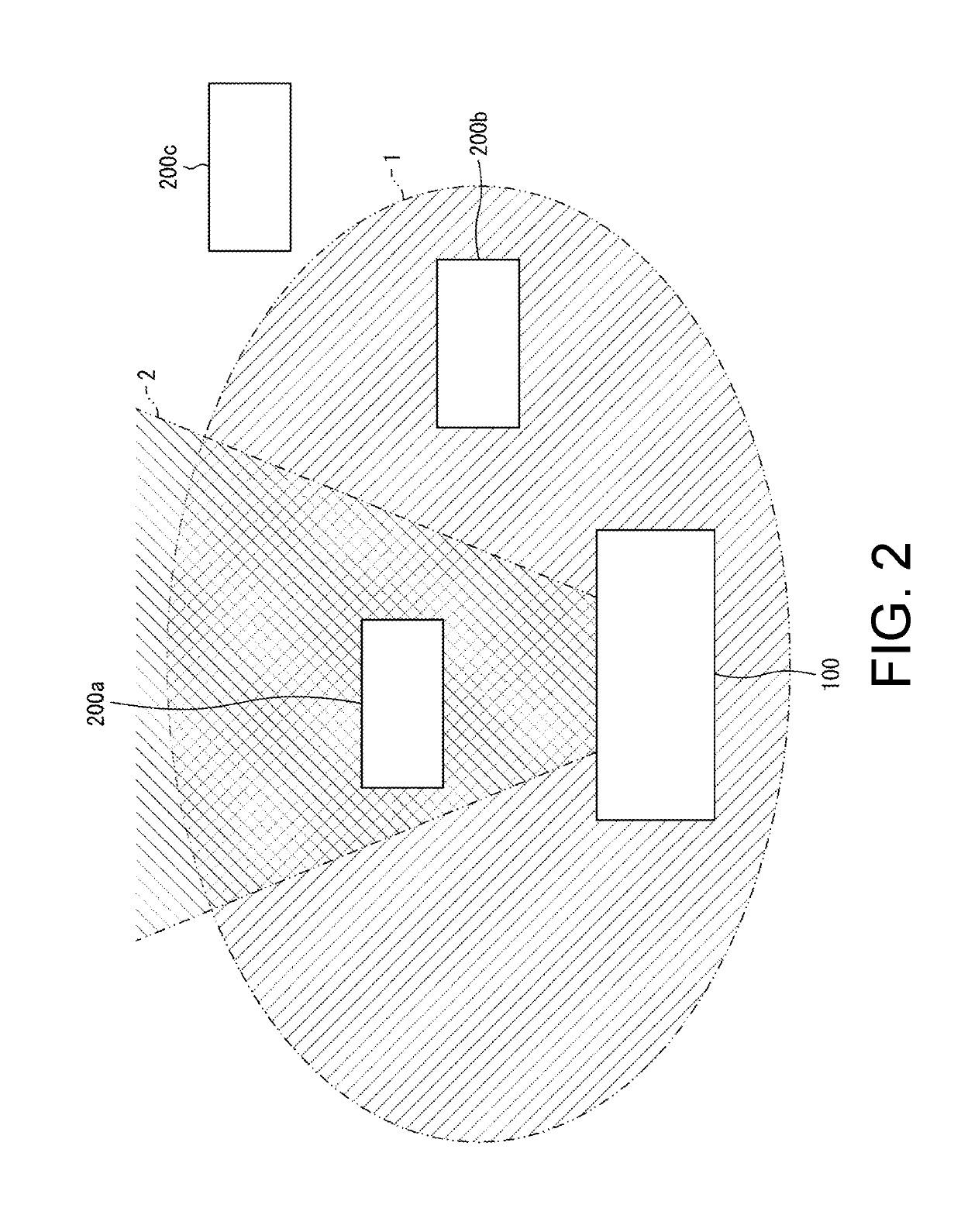
[0040]One example of a view to which the disclosure is applied will be described with reference to FIG. 1. FIG. 1 schematically illustrates one example of a tag communication system including a tag communication device 100 according to this embodiment. The tag communication device 100 performs an operation for RFID tags 200 present on a production line through radio communication (this radio communication is performed through communication units 110 and 210). An example of an operation performed by the tag communication device 100 for the RFID tag 200 includes writing / reading information stored in a storage unit 240 of the RFID tag 200.

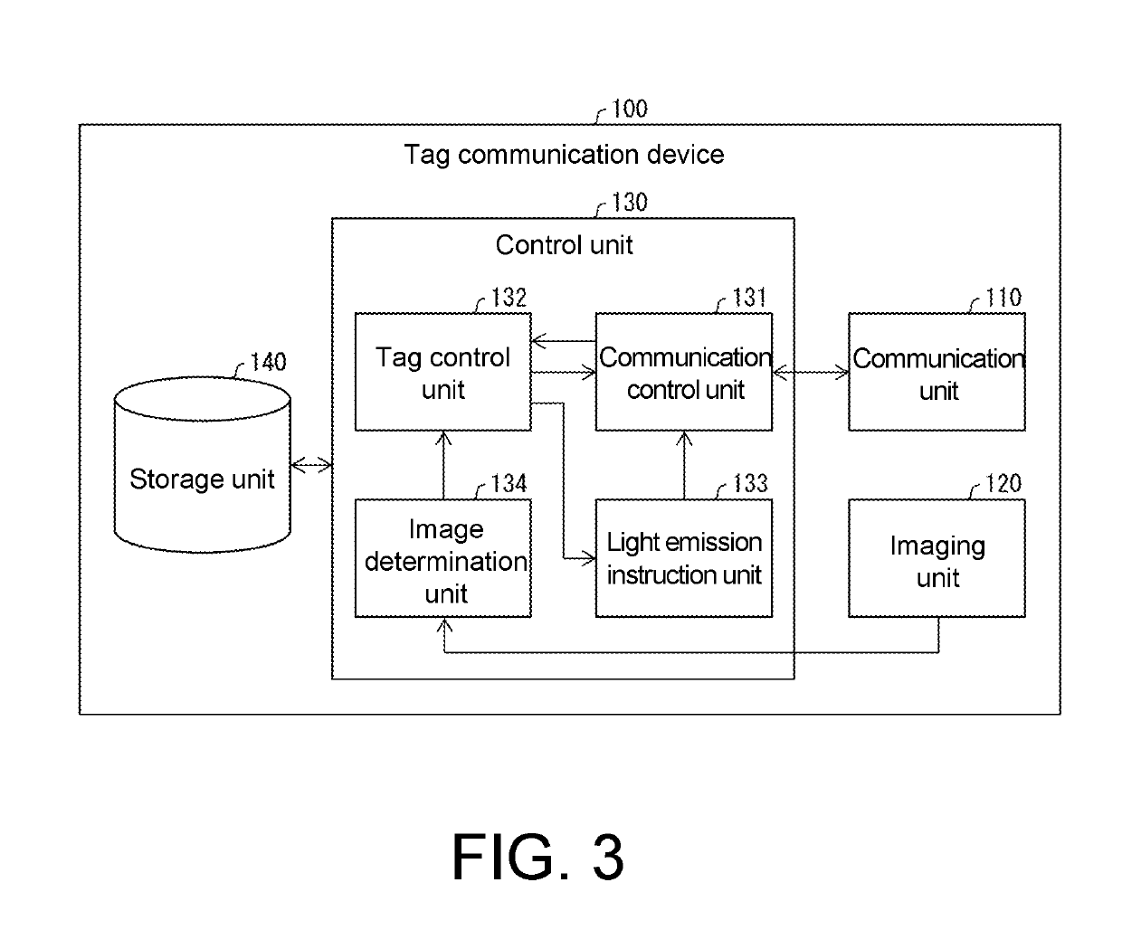
[0041]In this embodiment, a control unit 130 of the tag communication device 100 causes a light emitting unit 220 included in the RFID tag 200 to emit light. Then, the control unit 130 detects light emission of the light emitting unit 220 on the basis of image information acquired by an imaging unit 120. As a result, the tag com...


PUM


Abstract

A tag communication device performing radio communication with an RFID tag includes a light emitting unit. The tag communication device includes a communication unit, an imaging unit, and a control unit. The control unit (i) acquires a tag ID of RFID tags present in the communicable range of the communication unit, (ii) transmits a light emission instruction to some of RFID tags corresponding to the acquired tag ID, (iii) determines presence / absence of light emission of the light emitting unit based on the light emission instruction within an imaging area of the imaging unit on the basis of a result of imaging acquired by the imaging unit, and (iv) performs a predetermined operation for an RFID tag to which the light emission instruction has been transmitted in a case in which it is determined that light emission of the light emitting unit based on the light emission instruction is present.

Description

CROSS-REFERENCE TO RELATED APPLICATION[0001]This application claims the priority of Japan patent application serial no. 2018-082278, filed on Apr. 23, 2018. The entirety of the above-mentioned patent application is hereby incorporated by reference herein and made a part of this specification.BACKGROUNDTechnical Field[0002]The disclosure relates to a tag communication device performing radio communication with an RFID tag including a light emitting unit, a control method thereof, and a control program.Description of Related Art[0003]Radio frequency identification (RFID) technologies are technologies for reading information of an RFID tag or writing information in an RFID tag by performing radio communication with the RFID tag and are used in various industrial fields. As one example thereof, there is an application for articles on production lines. In other words, an RFID tag is attached to each article on a production line, and the progress of various production processes is monitor...

Claims


Application Information

Patent Timeline
IPC IPC(8): G06K19/07G06K7/10G06K7/00H04Q9/00
CPCG06K7/0008G06K19/0723H04Q9/00G06K7/10415H04Q2209/47G06K19/08G06K17/0029G06K7/10079G06K7/10128
Inventor MOTOSHIMA, HIROAKIYOSHIDA, TATSUOMATSUI, SHUICHI
Owner ORMON CORP
Learn More