
Thin-film magnetic head having a high recording density and frequency

Inactive Publication Date: 2006-08-08
TDK CORPARATION
View PDF9 Cites 0 Cited by
  • Summary
  • Abstract
  • Description
  • Claims
  • Application Information

AI Technical Summary

Benefits of technology

[0022]In order to solve the problems described above, an object of the present invention is to provide a thin-film magnetic head capable of performing accurate magnetic reco

Problems solved by technology

That is, leakage flux is generated at a location other than the vicinity of the gap layer 4, and particularly when recording frequency is increased, there is a problem in that accurate recording c

Method used


Image

  • Thin-film magnetic head having a high recording density and frequency
  • Thin-film magnetic head having a high recording density and frequency
  • Thin-film magnetic head having a high recording density and frequency

Examples


examples

[0262]The relationship between the P content in NiP formed by plating and the saturated magnetic flux density were measured. The results are shown in FIG. 30.

[0263]When NiP formed by plating was not heated, the NiP was in a nonmagnetic state when the P content was not less than 11 mass percent. In this state, the NiP had an amorphous structure.

[0264]In addition, the relationship between the P content in NiP formed by plating and the saturated magnetic flux density were measured when NiP formed by plating was heated to about 200° C., to about 240° C. and to about 300° C.

[0265]When amorphous NiP in a non-magnetic state under non-heating condition was heated, the NiP turned into a crystalline material and had magnetic properties depending on the P content.

[0266]As can be seen from the FIG. 30, when the P content in the NiP was not less than about 12.5 mass percent, even though the NiP was heated at about 200° C., to about 240° C., and to about 300° C., an amorphous structure of the NiP...


PUM


Abstract

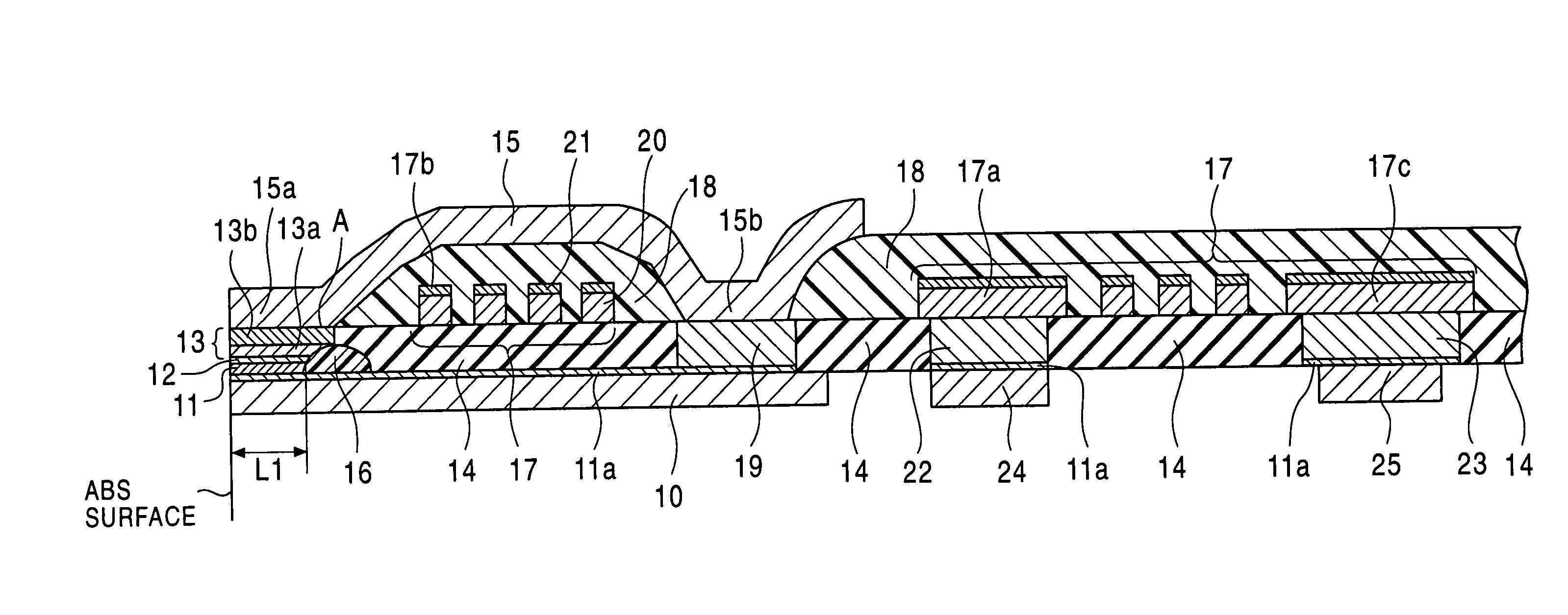
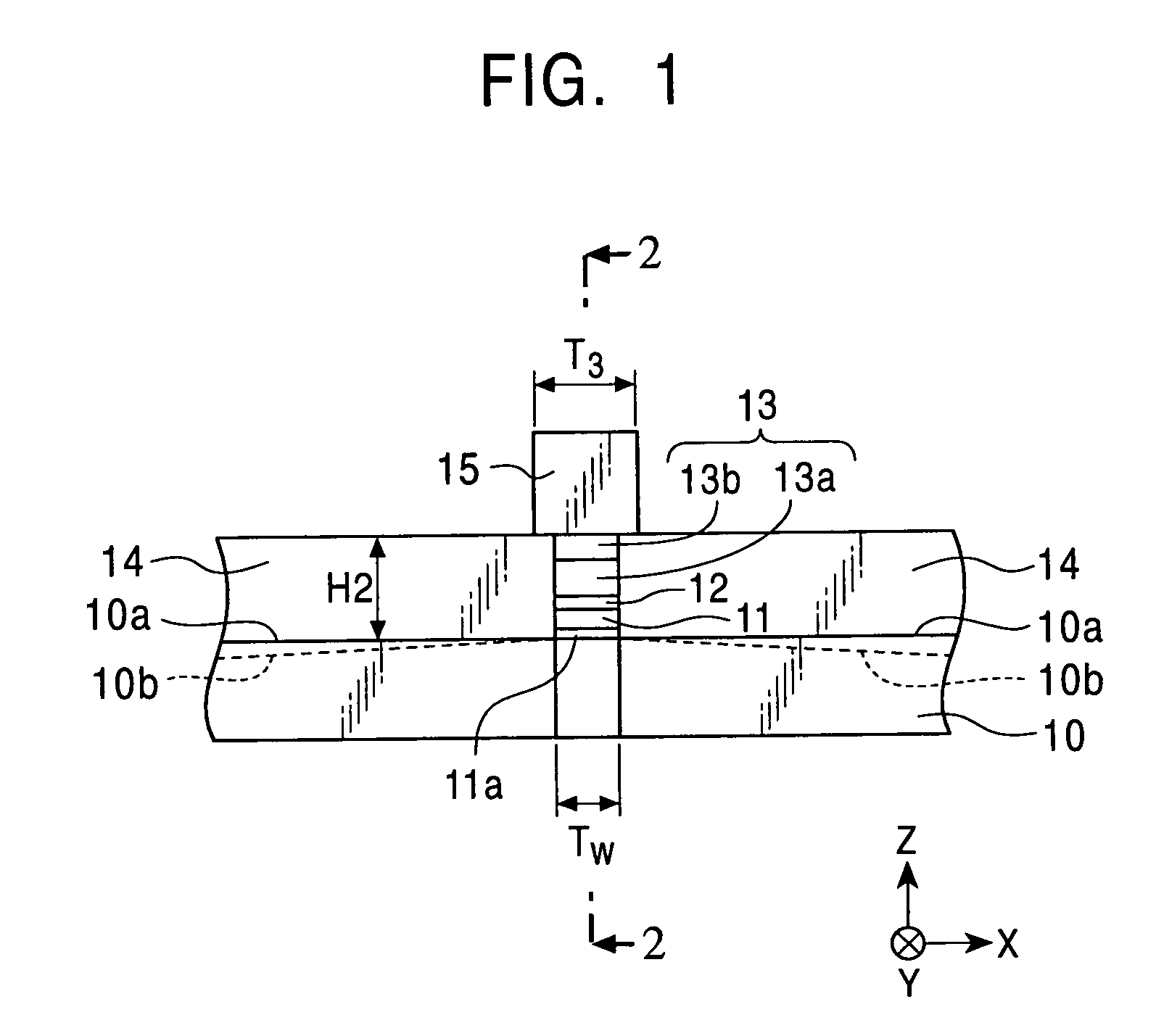
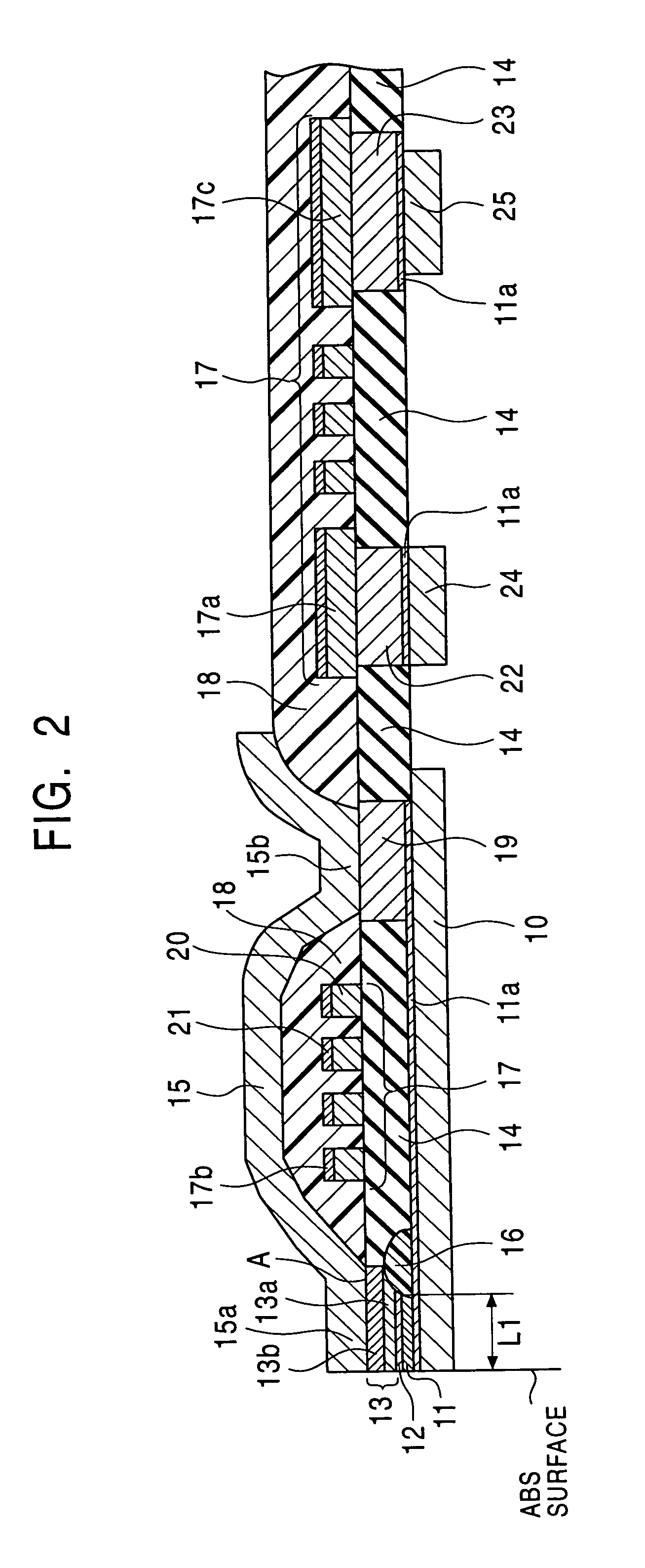
A gap depth determining insulating layer is formed on a lower core layer. A curved face is formed on a front edge face of the gap depth determining insulating layer so as to gradually depart from an ABS surface from the bottom at the lower core layer to the top of the curved face. A back end of an upper magnetic layer can be formed on the gap depth determining insulating layer, whereby the volume of the upper magnetic layer can be increased while a gap depth is maintained at a predetermined length.

Description

BACKGROUND OF THE INVENTION[0001]1. Field of the Invention[0002]The present invention relates to recording thin-film magnetic heads used, for example, in floating type magnetic heads. More particularly, the present invention relates to a thin-film magnetic head generating leakage flux at a satisfactory location in the vicinity of a gap layer so as to fulfill the requirements for high recording density and high recording frequency, and relates to a manufacturing method therefor.[0003]2. Description of the Related Art[0004]FIG. 31 is a partial front view showing the structure of a conventional thin-film magnetic head (inductive head), FIG. 32 is a partial cross-sectional view of the thin-film magnetic head taken along the line 32—32 in FIG. 31 and observed from the direction indicated by the arrow shown therein.[0005]Reference numeral 1 in FIGS. 31 and 32 indicates a lower core layer composed of a magnetic material such as a permalloy, and an insulating layer 9 is formed on the lower ...

Claims


Application Information

Patent Timeline
IPC IPC(8): G11B5/147G11B5/23G11B5/31G11B31/02
CPCG11B5/23G11B31/02G11B5/3116G11B5/3133
Inventor YAZAWA, HISAYUKIOKI, NARUAKIKOBAYASHI, KIYOSHIKOYAMA, AKIRAKANADA, YOSHIHIROIKEGAMI, LEGAL REPRESENTATIVE, HIROMIIKEGAMI, LEGAL REPRESENTATIVE, CHIAKIIKEGAMI, DECEASED, MASAKI
Owner TDK CORPARATION
Learn More