Reception apparatus and non-transitory computer readable medium

Pending Publication Date: 2022-06-16
KDDI CORP +1
View PDF3 Cites 0 Cited by
  • Summary
  • Abstract
  • Description
  • Claims
  • Application Information

AI Technical Summary

Benefits of technology

The present invention allows for accurate frequency compensation in a reception apparatus. This means that the device can accurately adjust the frequency to ensure that signals are received correctly.

Problems solved by technology

However, with a modulation scheme having a high multi-value level, the maximum value of the permissible range of residual error is approximately 100 kHz, and in order to keep the residual error within the permissible range, the size of the discrete Fourier transform (“FFT size” hereinafter) must be about 105, which is difficult to process in real time.
However, the fourth power method becomes unstable when the optical communication system contains a large amount of noise.

Method used


Image

  • Reception apparatus and non-transitory computer readable medium
  • Reception apparatus and non-transitory computer readable medium
  • Reception apparatus and non-transitory computer readable medium

Examples


first embodiment

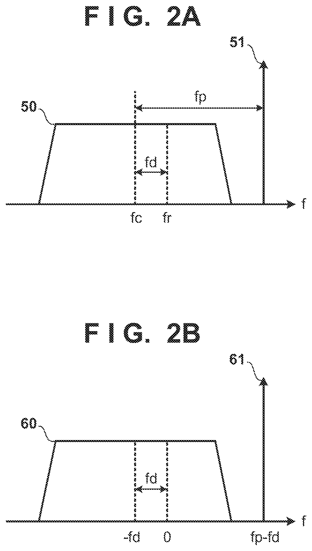
[0022]FIG. 1 is a block diagram of a reception apparatus according to the present embodiment. In the present embodiment, a transmission apparatus adds pilot light to modulated light carrying information, and transmits an optical signal including the modulated light and the pilot light. FIG. 2A illustrates the optical signal transmitted by the transmission apparatus and received by the reception apparatus. The optical signal includes modulated light 50 and pilot light 51. Note that a center frequency of the modulated light is assumed to be fc, and the frequency of the pilot light is assumed to be higher than fc by fp. Note also that as illustrated in FIG. 2A, although the frequency of the pilot light 51 is higher than that of the modulated light 50 in present embodiment, the configuration may be such that the frequency is lower.

[0023]A light source 10 of the reception apparatus generates local light and outputs the local light to a reception unit 11, and the reception unit 11 perform...

second embodiment

[0043]A second embodiment will be described, focusing on the differences from the first embodiment. FIG. 5 is a block diagram of a reception apparatus according to the present embodiment. Note that function blocks that are the same as those of the reception apparatus of the first embodiment illustrated in FIG. 1 are given the same reference signs, and will not be described.

[0044]In the first embodiment, after the frequency shift by the shift unit 18, the pilot signal 61 was converted back to a signal in the time domain by the IFFT unit 19, and downsampling was then performed by the DS unit 20. In the present embodiment, after the frequency shift by the shift unit 18, downsampling is performed in the frequency domain before converting the signal to the time domain. Accordingly, a DS unit 22 selects a predetermined number of consecutive frequency samples, including DC (frequency 0), from the frequency samples output by the shift unit 18. Note that the frequency samples selected by the...


PUM


Abstract

A reception apparatus includes: a receiving unit configured to coherently detect an optical signal and output an electrical signal containing a modulated signal and a pilot signal; a first compensating unit configured to detect a frequency of the pilot signal by performing a DFT of the electrical signal, and determine and compensate for frequency error in the electrical signal based on a reference frequency; a frequency converting unit configured to convert the frequency of the pilot signal after the compensating such that the frequency of the pilot signal is lowered by the reference frequency; and a second compensating unit configured to determine frequency error in the modulated signal after the compensating by performing a DFT on the pilot signal after the frequency converting and detecting a frequency of the pilot signal after the frequency converting.

Description

CROSS-REFERENCE TO RELATED APPLICATION(S)[0001]This application is a continuation of International Patent Application No. PCT / JP2020 / 033997 filed on Sep. 8, 2020, which claims priority to and the benefit of Japanese Patent Application No. 2019-169498 filed on Sep. 18, 2019, the entire disclosures of which are incorporated herein by reference.BACKGROUND OF THE INVENTIONField of the Invention[0002]The present invention relates to a frequency compensation technique in a reception apparatus of a coherent optical communication system.Description of the Related Art[0003]One method for increasing the transmission rate in a coherent optical communication system is to increase the multi-value level of the modulation scheme used. In a coherent optical communication system, the reception apparatus performs demodulation by compensating for a frequency difference between the light source of the reception apparatus and the light source of the transmission apparatus (hereinafter referred to simply...

Claims


Application Information

Patent Timeline
IPC IPC(8): H04B10/61H04B10/63
CPCH04B10/6164H04B10/612H04B10/63G02F2/00H04B10/0775H04B10/616H04B2210/075
Inventor BEPPU, SHOHEITSURITANI, TAKEHIROIGARASHI, KOJISHIGIHARA, MASAHIROKIKUTA, MASAHIRO
Owner KDDI CORP
Why Eureka
Try Eureka