Two-part fence base

a fence base and two-part technology, applied in the direction of traffic signals, applications, roads, etc., can solve the problems of reducing the stability of the fence, the panel at the end of a temporary fence will be very poorly supported, and the anchor block is unsuitable for acting as hinges or bearings

Inactive Publication Date: 2008-10-02
KELVINDALE PROD
View PDF2 Cites 19 Cited by
  • Summary
  • Abstract
  • Description
  • Claims
  • Application Information

AI Technical Summary

Problems solved by technology

This places them outside the permitted maximum weight, which in some jurisdictions at least, may be lifted by a male person due to health and safety issues.
A disadvantage of this arrangement is that each of the stiles of two adjacent fence panels is supported within one only of the pair of anchor blocks (when inserted into the central pair of apertures) so that with free sliding movement between the interlocking parts, there is likely to be reduced stability of the fence when subjected to lateral loading.
Apart from the complexity of manufacture, a particular disadvantage in use of this arrangement is that the panels at the ends of a temporary fence will be very poorly supported, since a single upright inserted through the aperture of the hoops, which are adapted to hold two uprights, will not be secured.
A further disadvantage of both the above disclosures of the prior art, lies in the fact that, particularly in the case of AU2004208695, the anchor blocks are unsuitable for acting as hinges or bearings when it is desired to operate one or a pair of panels of the temporary fence as an access gate.
Nor is there any provision in either of the pairs of anchor blocks of these prior art disclosures, for additional securing means; both relying purely on the mass of the blocks to maintain the fence in an upright position.

Method used


Image

  • Two-part fence base
  • Two-part fence base
  • Two-part fence base

Examples


Embodiment Construction

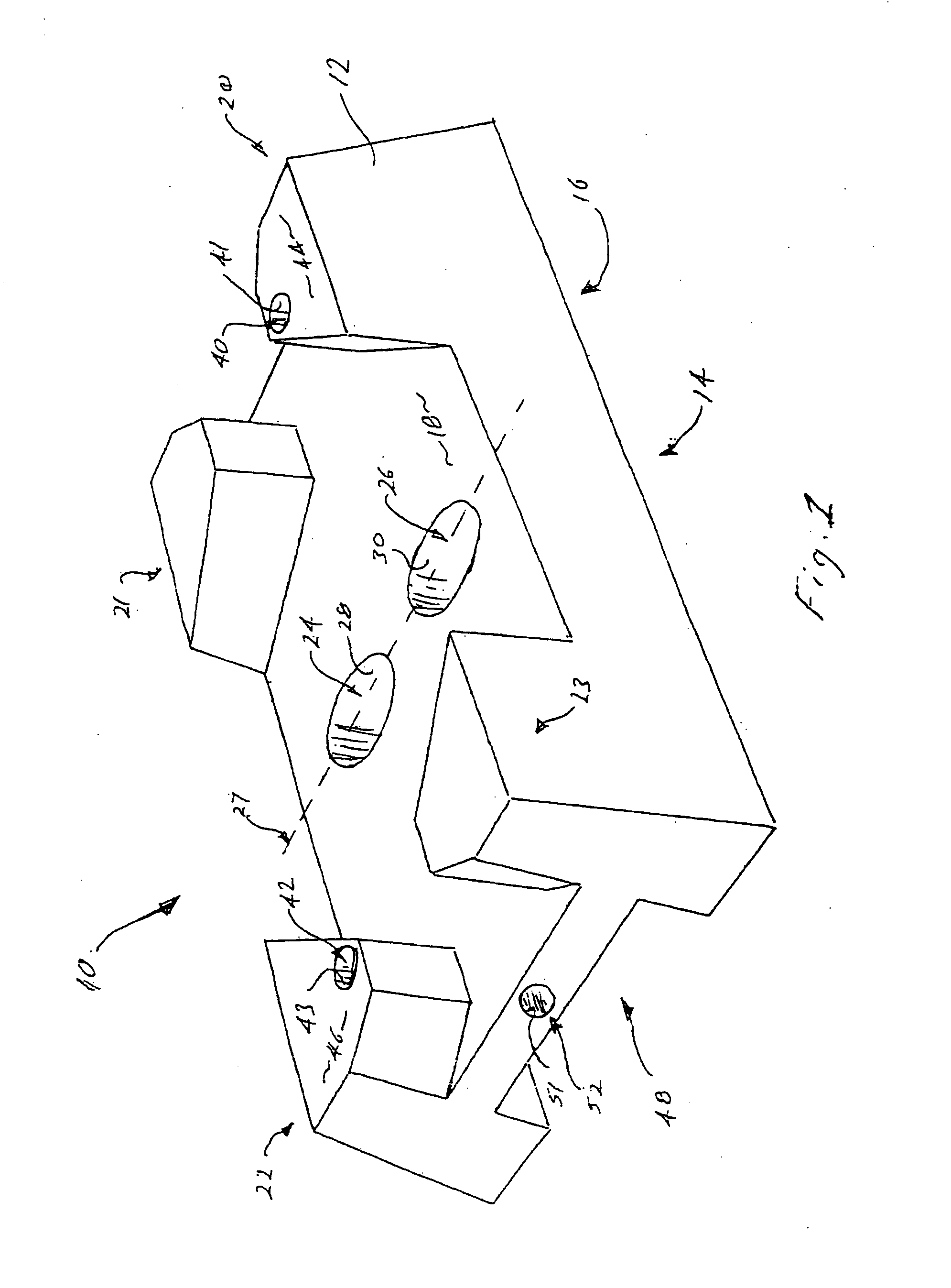
[0065]With reference to FIG. 1, a base portion 10 of a fence base is comprised of a shell 12 moulded in some suitable plastic. Shell 12 is formed as a generally rectangular prism having a rectangular base 14 open at its underside 16 as may be seen from the view from below of FIG. 6.

[0066]Shell 12 has an upper surface 18 parallel with rectangular base 14. The sides of shell 12 preferably taper inwardly to some extent as can best be seen in the side elevation and end elevation views of FIGS. 4 and 7. Projecting upwardly at each corner area of upper surface 18, are projections 20 to 23. Upper surface 18 is provided with apertures 24 and 26 arranged side by side and disposed along the transverse centre line 27 of upper surface 18.

[0067]Apertures 24 and 26 communicate with formers 28 and 30 respectively, integrally moulded with shell 12 and extending downwardly from the underside of upper surface 18 to the level of rectangular base 14 as best seen in the hidden detail of FIG. 4. Formers ...


PUM

PropertyMeasurementUnit
weightaaaaaaaaaa
weightaaaaaaaaaa
lengthaaaaaaaaaa

Abstract

An anchor assembly for a temporary fence; said assembly comprising a base portion and a superposed insert portion; each said base portion and said superposed insert portion comprising a composite of a shell open at the underside, and a settable material filling said shell; and wherein respective pairs of formers integral to each said shell of said base portion and said superposed portion, define substantially vertical pairs of passages through said base portion and said superposed insert portion; said passages arranged so that when said base portion and said superposed insert portion are assembled together, respective pairs of said passages are in vertical alignment; said passages adapted for receiving therethrough respective ends of uprights of adjacent panels of said temporary fence; said ends passing through both said superposed insert portion and said base portion.

Description

[0001]The present invention relates to temporary fences such as typically found at building sites and, more particularly to the base or anchor blocks with apertures into which the uprights of panels of such fences may be inserted and so supported.BACKGROUND[0002]The use of temporary fences made up of panels comprising pairs of uprights and stringers with infills of woven wire mesh, supported in concrete blocks, has become a common feature of building sites and other areas requiring temporary enclosure. In this arrangement, the anchor blocks are provided with one or more apertures into which the adjacent uprights or stiles of a pair of adjoining panels can be inserted.[0003]To be effective in supporting the substantial weight of the fence panels and resisting the forces such as wind loading, which may be applied to them, the anchor blocks themselves must be of substantial size and weight, preferably at least 35 Kg. This places them outside the permitted maximum weight, which in some ...

Claims


Application Information

Patent Timeline
Patent Type & Authority Applications(United States)
IPC IPC(8): E04H17/00B21F29/00B21F27/00
CPCE01F9/0124E04H12/2238Y10T29/49947Y10T29/49826Y10T29/4998E04H17/22E01F9/692E04H17/009
Inventor DEHLSEN, BRIAN
Owner KELVINDALE PROD
Why Eureka
Try Eureka