Structure of a hooked fastener

a technology of hooking and fastening plate, which is applied in the direction of construction fastening device, fastening means, etc., can solve the problem that the hooking plate cannot be smoothly moved

Inactive Publication Date: 2008-10-02
JYUN HAO
View PDF0 Cites 17 Cited by
  • Summary
  • Abstract
  • Description
  • Claims
  • Application Information

AI Technical Summary

Problems solved by technology

However, the holding member and the covering are made plastics, and will be caused to change shape by pressure from the contents of a wall plank member when they together are inserted in the wall plank member.
Therefore, the guide grooves of the holding member change their shape, and can't effectively serve as the guiding means for the hooked plate together with the post-shaped protrusions, and in turn the hooked plate can't be smoothly moved.

Method used


Image

  • Structure of a hooked fastener
  • Structure of a hooked fastener
  • Structure of a hooked fastener

Examples


Embodiment Construction

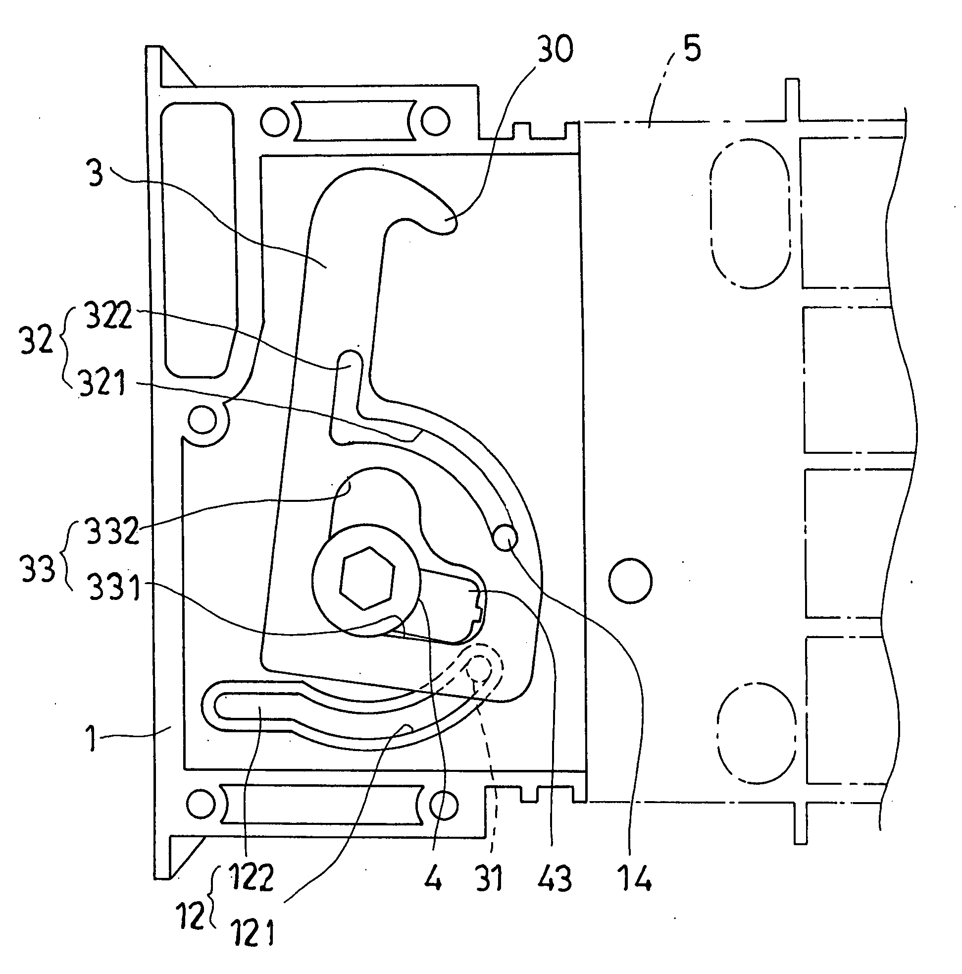
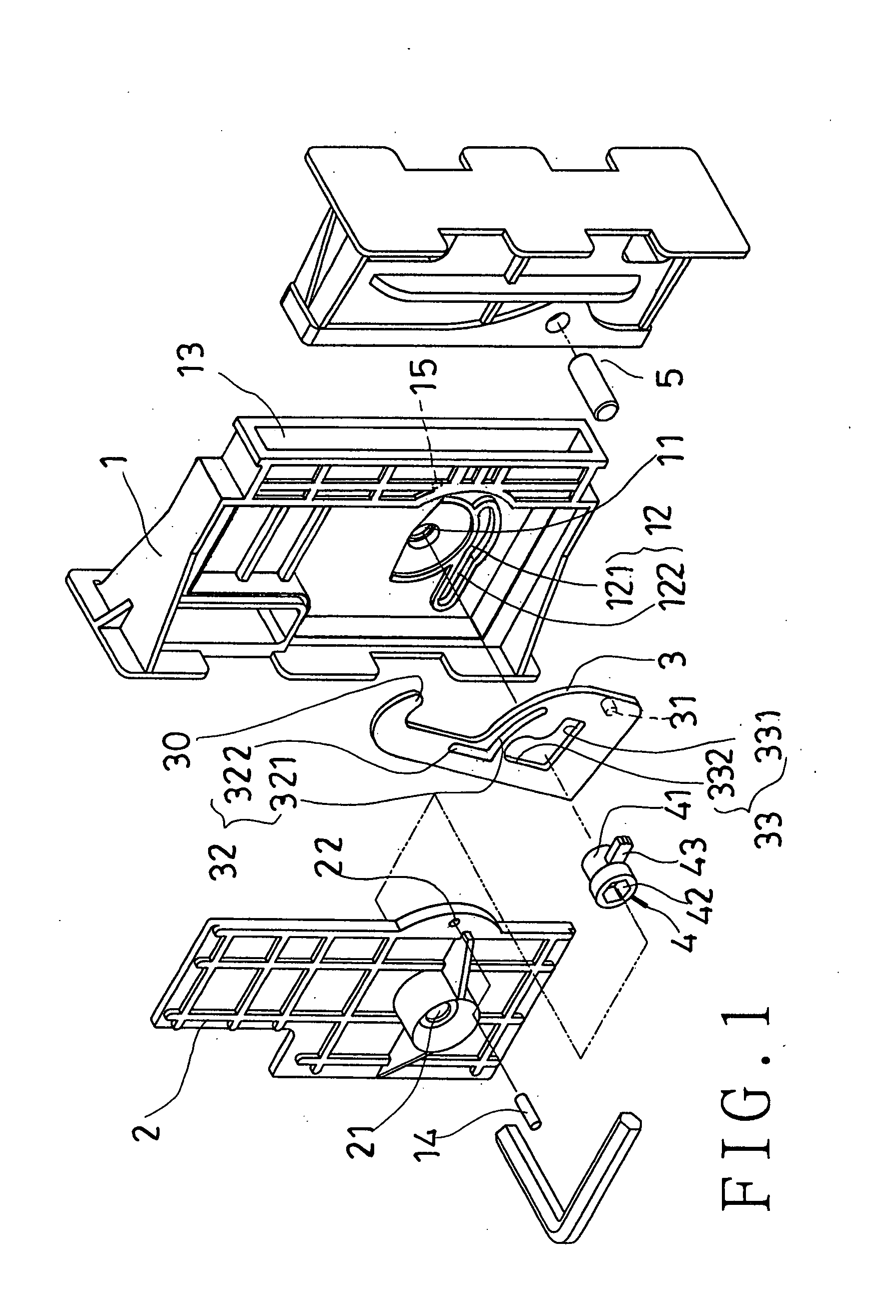
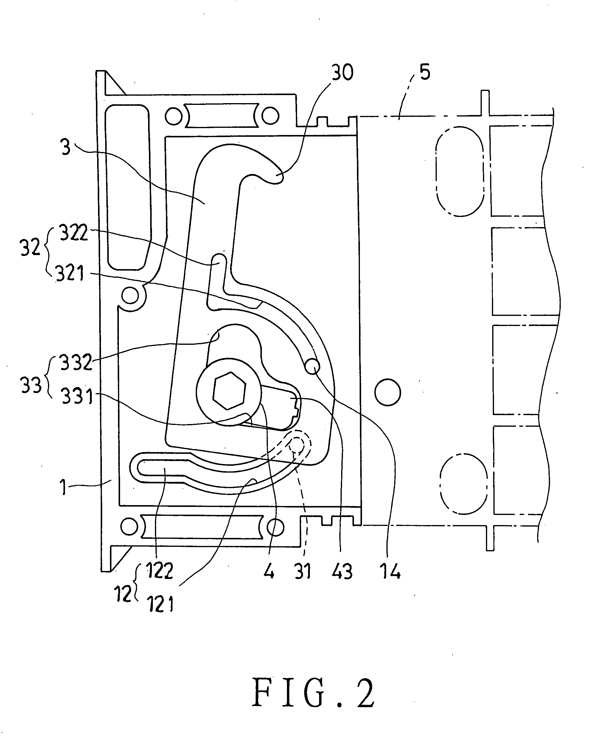
[0027]Referring to FIG. 1, an improvement on a hooked fastener structure of the present invention includes a holding member 1, a covering part 2, a hooked plate 3, a rotary sleeve 4, and a coupling piece 5 for the hooked plate 3 to be hooked over.

[0028]The hooked plate 3 is received in and supported with the holding member 1. The holding member 1 has a through hole 11, through which the rotary sleeve 4 is passed. The holding member 1 has at least one and no more than three rails 12 around the through hole 11 on one side thereof. The hooked plate 3 is positioned around the rotary sleeve 4 in such a manner as to be caused to move by the rotary sleeve 4 when the rotary sleeve 4 is angularly displaced. The hooked plate 3 has on a first side thereof several post-shaped protrusions 31 each received in a corresponding said rail 12 of the holding member 1. Each of the rails 12 has a curved section 121 for serving to guide the hooked plate 3 together with a corresponding said post-shaped pro...


PUM


Abstract

A hooked fastener includes a holding member, a covering on the holding member, a hooked plate and a rotary sleeve between the holding member and the covering, and a coupling piece for the hooked plate to be hooked over; the holding member has a rail, and the hooked plate has on one side a post-shaped protrusion received in the rail; the rail of the holding member and the post-shaped protrusion of the hooked plate together will serve as a guiding means for the hooked plate when the rotary sleeve is wrenched so as to move the hooked plate; the hooked plate has a guide rail on the other side, and the holding member has a guide rod secured therein and passed through the guide rail of the hooked plate; the guide rail and the guide rod together also will serve as a guiding means for the hooked plate.

Description

BACKGROUND OF THE INVENTION[0001]1. Field of the invention[0002]The present invention relates to an improvement on a hooked fastener, more particularly one, which can be smoothly operated so as to make a hooked plate tightly hooked over a coupling piece thereof.[0003]2. Brief Description of the Prior Art[0004]Cold storages and prefabricated houses comprise many wall plank members, and several coupling devices fastening every two adjacent ones of the wall plank members to each other. Such a coupling device usually includes a hooked plate, a rotary sleeve, a holding member, and a coupling piece.[0005]The hooked plate has a hook portion, and a through hole, and is held in the holding member. The rotary sleeve has an acting protruding portion, and is passed through the through hole of the hooked plate such that the rotary sleeve can be wrenched in order for the acting protruding portion to cause displacement of the hooked plate. The coupling piece has a rod part, and the hooked plate wi...

Claims


Application Information

Patent Timeline
Patent Type & Authority Applications(United States)
IPC IPC(8): E05C19/10
CPCE04B1/6183E05C5/00E05C19/10Y10T292/0911
Inventor HUANG, CHIEN-HOA
Owner JYUN HAO
Why Eureka
Try Eureka