Modular airbag housing and method of manufacture

a module-type, airbag technology, applied in the direction of pedestrian/occupant safety arrangement, vehicular safety arrangments, vehicle components, etc., can solve the problems of airbag housings that are not widely used, airbag housings designed for particular sub-components may be unusable, and airbag housings intended for use in sport utility vehicles, for example, may not be suitable for mounting in compact cars

Inactive Publication Date: 2006-08-29
TK HLDG
View PDF28 Cites 14 Cited by
  • Summary
  • Abstract
  • Description
  • Claims
  • Application Information

AI Technical Summary

Benefits of technology

[0005]It is an object of the present invention to provide a modular airbag housing that is relatively simple to manufacture and versatile in size, configuration, and accommodation of varying airbag inflators.
[0007]In another aspect, an airbag housing is provided that includes an inflator retainer attached thereto. The inflator retainer has a first half and a second half. The first half includes an outer surface having a flange extending therefrom. The second half includes an outer surface having a plurality of orifices penetrating therethrough and a second flange extending therefrom. Attachment of the first and second halves allows an inflator to be secured therein, and alignment of the flanges allows an airbag to be secured therebetween.

Problems solved by technology

Because of the strict sizing and design requirements, airbag housings generally do not enjoy a high degree of versatility.
An airbag housing designed for particular sub-components may be unwieldy or even unusable in circumstances where different sub-components are desirable.
Likewise, a housing intended for use in a sport utility vehicle, for example, may not be suitable for mounting in a compact car due to the differing dimensions of the vehicle structures.
While the end product is relatively rigid, and simple to fully assemble, a significant amount of waste material can be produced from the large number and volume of stampings required.
Additionally, it is often necessary to operate the equipment at relatively high tonnages, consuming substantial amounts of power.
Moreover, retooling is often necessary where housings are to be manufactured to differing specifications, increasing both costs and equipment downtime.

Method used


Image

  • Modular airbag housing and method of manufacture
  • Modular airbag housing and method of manufacture
  • Modular airbag housing and method of manufacture

Examples


Embodiment Construction

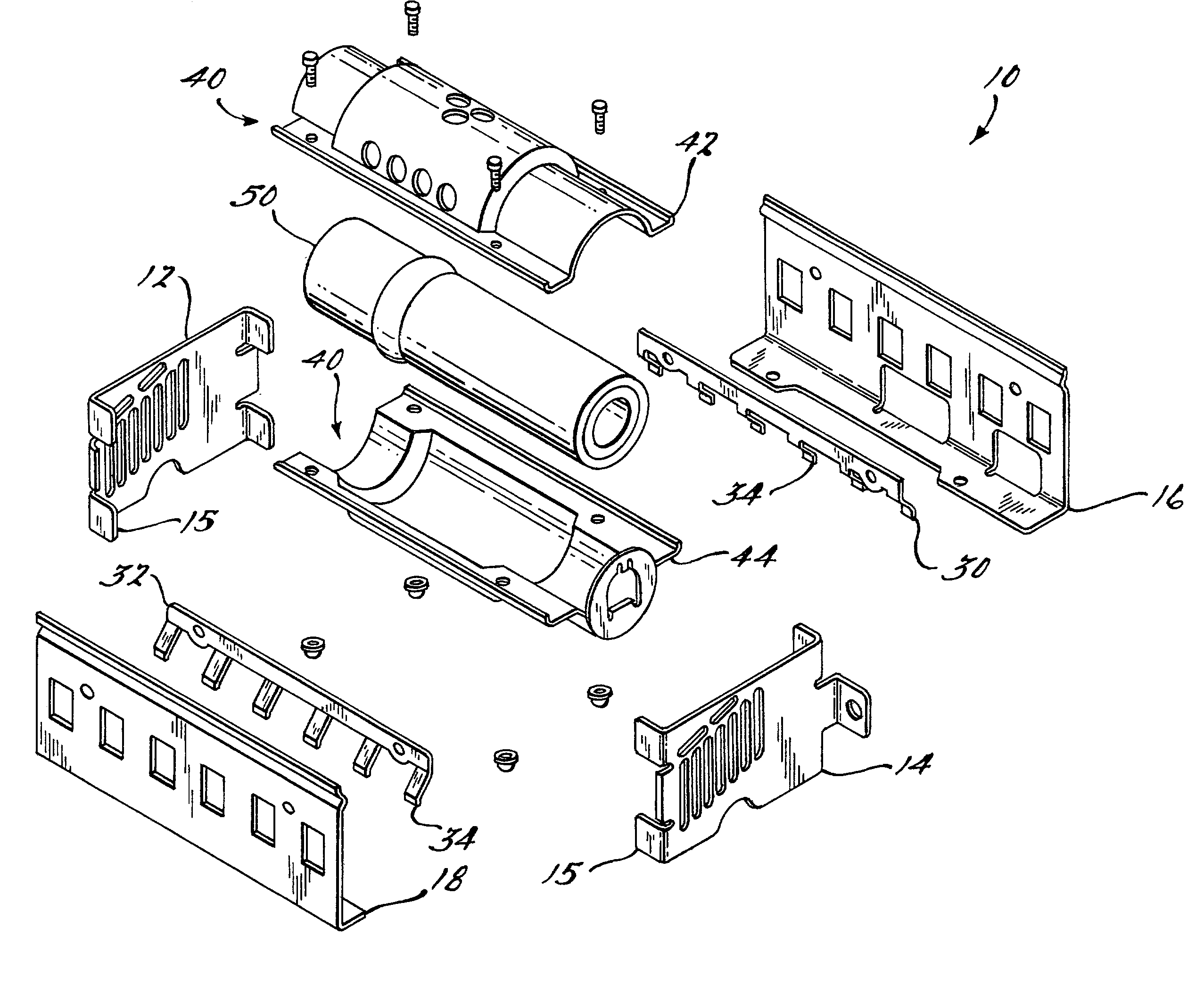
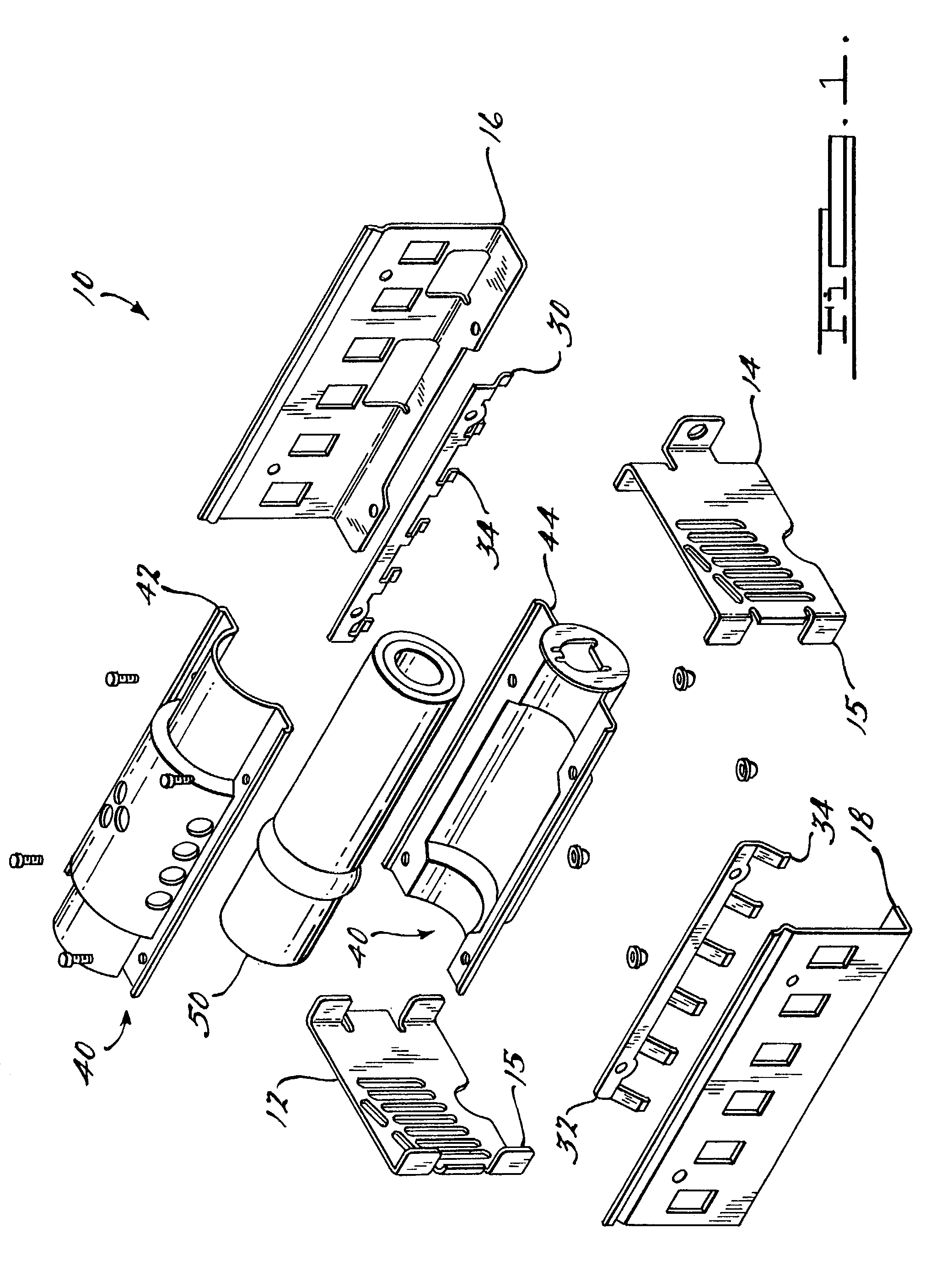
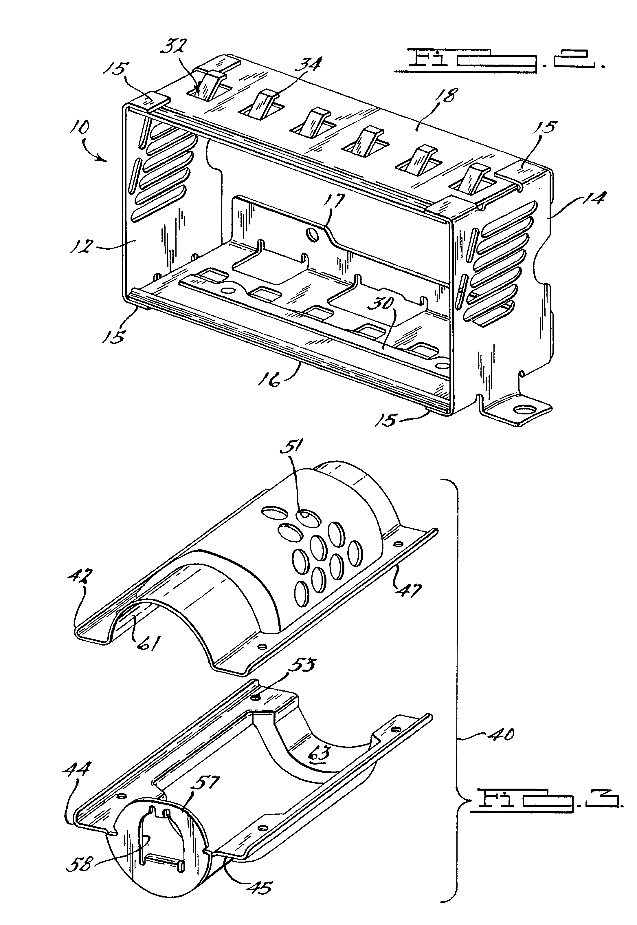
[0012]Referring to FIG. 1, there is shown an exploded view of a modular airbag housing assembly 10 according to a preferred embodiment of the present invention. Housing assembly 10 is preferably mounted in a vehicle dashboard, where it stores a folded airbag cushion that can be deployed toward a vehicle interior to protect an occupant in the event of a crash or sudden deceleration. Housing assembly 10 includes, for example, a first modular end plate 12 and a second modular end plate 14, which are preferably substantially similar in shape and construction. Housing assembly 10 further includes a first side plate 16, or lower plate, and a second side plate 18, or upper plate. The various housing plates utilized in the construction of the present invention are preferably substantially planar. The pieces need not be perfectly flat or smooth, however, in a preferred embodiment the housing plates arc formed with conventional metal stamping equipment, and for ease of processing as well as a...


PUM


Abstract

A modular airbag housing and a method for its manufacture are provided. The modular airbag housing is constructed from a plurality of pieces, including a plurality of plates, at least two of which are modular, and an inflator retainer. The housing has a plurality of tabs for attaching to the vehicle. Two hook plates having a plurality of hook members may be attached to the housing. The inflator retainer includes a first half and a second half. Both halves of the retainer include a substantially arcuate outer surface and at least one flange, a securing of the halves fixing a portion of an airbag therebetween. The second half includes a plurality of inflation orifices for directing inflation gas from an inflator unit into an airbag attached to the inflator retainer.

Description

TECHNICAL FIELD[0001]The present invention relates generally to housings for vehicle inflatable restraint devices and methods for the manufacture thereof, and more particularly to such a housing having a plurality of modular members, and a method for its manufacture.BACKGROUND OF THE INVENTION[0002]A great variety of designs and manufacturing processes for airbag housings and related mounting hardware has developed over the years. Some of these housings provide specific mounting features for positioning and retaining the housing within a particular vehicle model, or class of vehicles. Similarly, a great degree of design specificity is often required for mounting and retaining various sub-components of the housing, for instance, the respective retainers for the inflator and for the airbag. Because of the strict sizing and design requirements, airbag housings generally do not enjoy a high degree of versatility. An airbag housing designed for particular sub-components may be unwieldy o...

Claims


Application Information

Patent Timeline
Patent Type & Authority Patents(United States)
IPC IPC(8): B60R21/16B60R21/20B60R21/217
CPCB60R21/2171
Inventor CHAVEZ, SPENCER WILLIAMTABOR, IV, WILLIAM DONALD
Owner TK HLDG
Why Eureka
Try Eureka