
Computer System with ID Tag

a computer system and id tag technology, applied in computing, error detection/correction, instruments, etc., can solve problems such as recording error data of computer systems, and achieve the effect of preventing disturbance during reading of rfid tags and ensuring electromagnetic compatibility of computer systems

Inactive Publication Date: 2008-10-02
FUJITSU SIEMENS COMP GMBH
View PDF14 Cites 3 Cited by
  • Summary
  • Abstract
  • Description
  • Claims
  • Application Information

AI Technical Summary

Benefits of technology

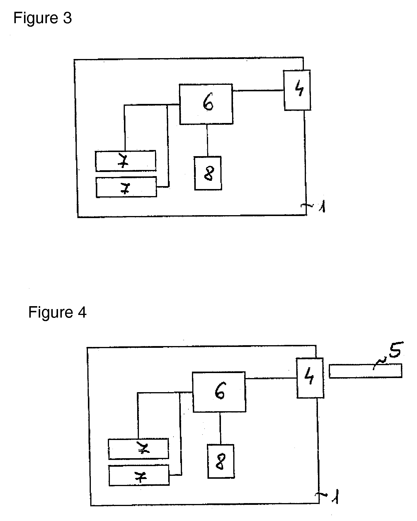
[0007]Specific data for the computer system are stored on the rating plate. For example, they are a serial number, hardware or software equipment in a delivery state or a connect load of the computer system. Likewise, with abnormal functioning of the computer system, error data of the computer system are recorded, which, for example, comprise data from the BIOS / error storage unit. Since these data are stored on the RFID tag, they can be recorded, for example, with a reading device by a user by simply reading the RFID tag and can be used both for inventory purposes and also to eliminate errors. The reading of the RFID tag can take place while the computer system is turned on or off or even if it is defective. The RFID tag can be a passive or an active RFID tag. The active RFID tag is provided with power, wherein the power supply preferably occurs via the computer system.
[0008]In a preferred embodiment, the RFID tag is located on a front shield of the housing. If the computer system is built into a server rack, then the front shield is freely accessible. In this way, the RFID tag is easily accessible and can be simply read. The RFID tag requires very little space, for example, a few millimeters and thus can be adapted to the size of the remaining space on the front shield. A large number of specific data of the computer system can be stored on the RFID tag and can be recorded simply with the reading device.
[0010]In another advantageous embodiment, the housing of the computer system has a recess in the area of the RFID tag. A metal surface on which the RFID tag is located can have a disturbing effect for reading of the RFID tag. The recess in the area of the RFID tag can prevent such a possible disturbance during reading of the RFID tag.
[0011]Advantageously, the housing of the computer system in an area of the RFID tag is made of plastic. In this way, a possible disturbance during reading of the RFID tag is prevented.
[0012]In another advantageous embodiment, the computer system in the area of the RFID tag has a metal shielding, at a distance from the tag, within the computer system. In this way, an electromagnetic compatibility (EMV) of the computer system is guaranteed.
[0013]Advantageously, data from the manufacture of the computer system are stored on the RFID tag as a rating plate. The RFID tag can, for example, be described with data from the delivery state of the computer system, immediately after its final assembly. Also, a buyer of the computer system has these data immediately available on the RFID tag, without the computer system having to be turned on or unpacked.

Problems solved by technology

Likewise, with abnormal functioning of the computer system, error data of the computer system are recorded, which, for example, comprise data from the BIOS / error storage unit.

Method used


Image

  • Computer System with ID Tag
  • Computer System with ID Tag
  • Computer System with ID Tag

Examples


Embodiment Construction

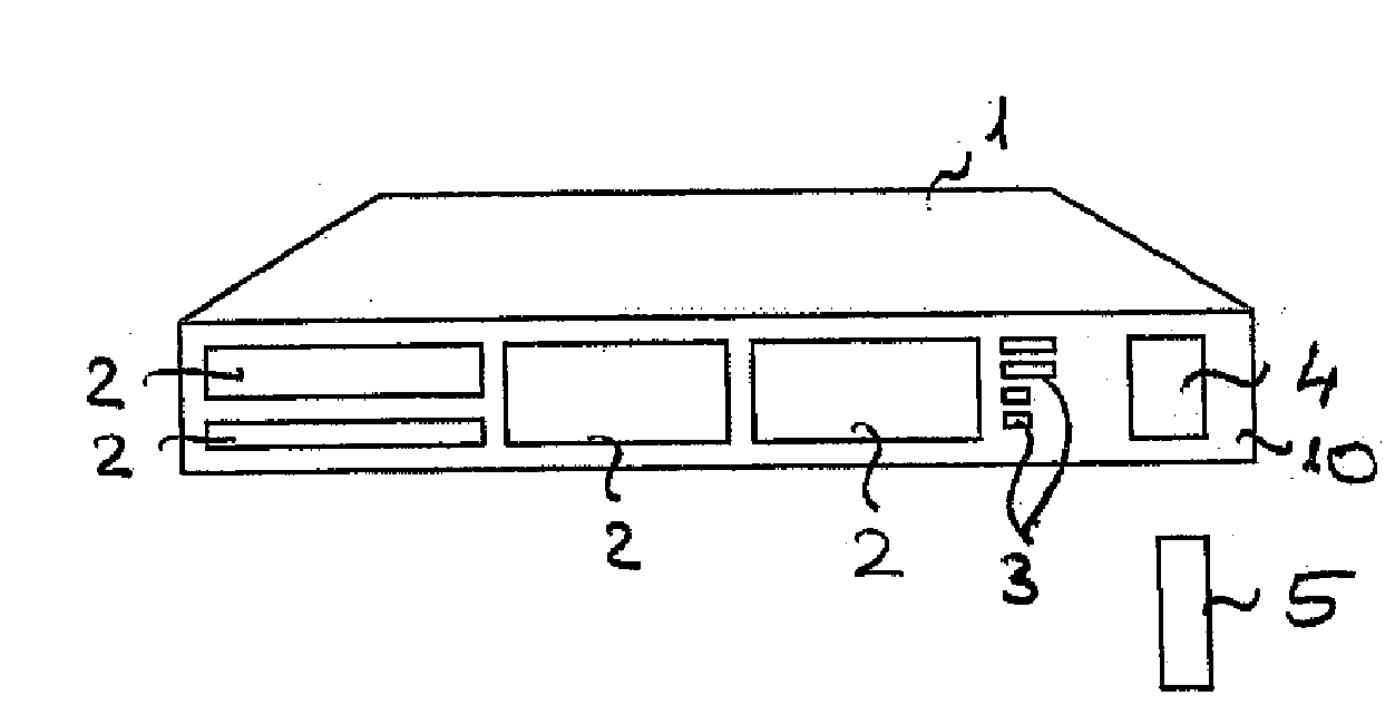
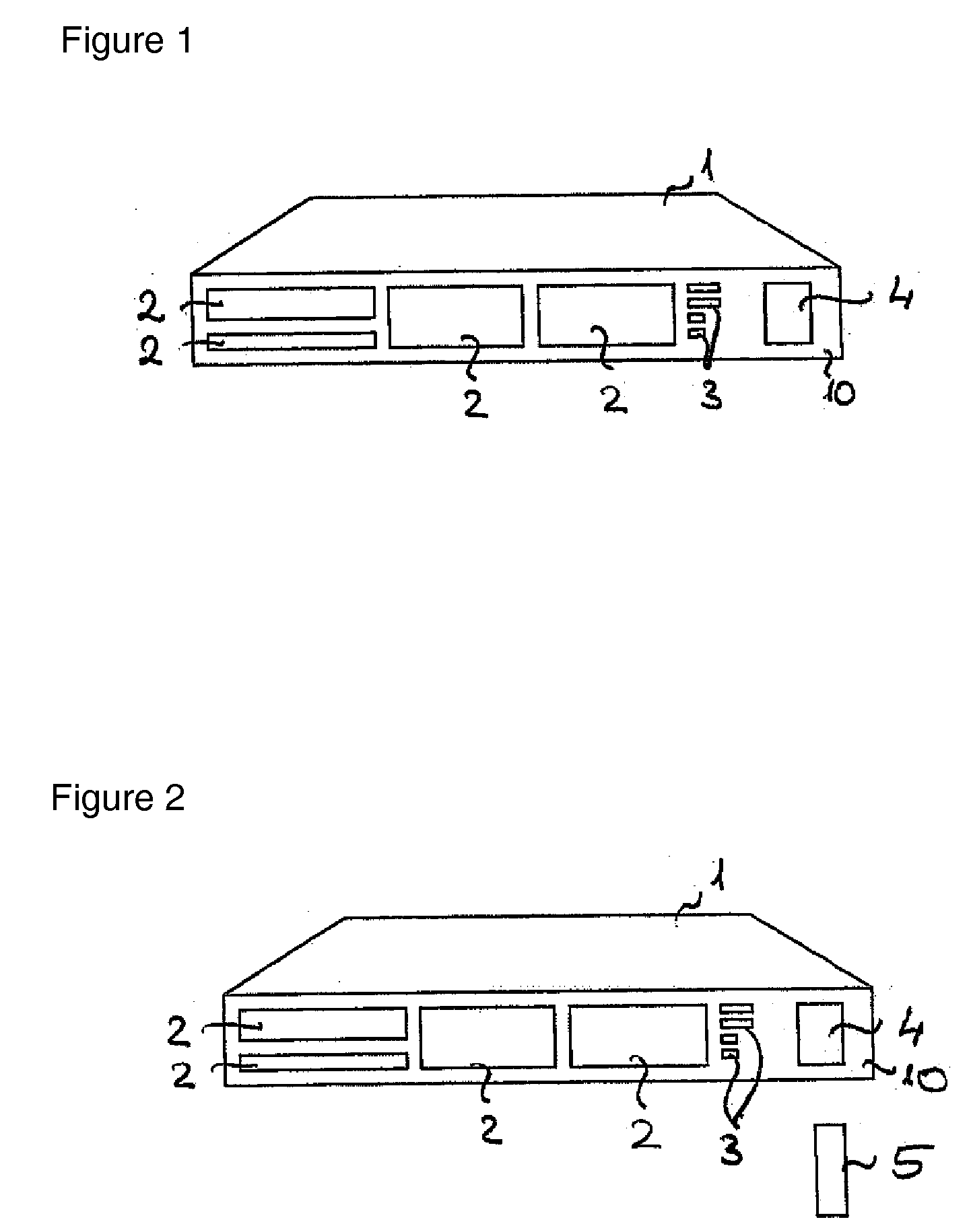
[0023]FIG. 1 shows, in a first exemplified embodiment, a computer system 1. The computer system 1 has a front shield 10, a large number of drives 2, connections 3, and an RFID tag 4. For better understanding of the drawing, the RFID tag 4 is represented greatly enlarged.

[0024]The drives 2 are located in slide-in units of the computer system 1 and are accessible via recesses in the front shield 10 of the computer system 1. The drives 2 are, for example, a CD-ROM drive, a DVD drive, a diskette drive, or hard disk drives. The connections 3 are provided, for example, designed as a PCI interface or to connect to a computer network.

[0025]The computer system 1 is, for example, a Primergy RX100 from Fujitsu Siemens and has a height of one height unit, also known as U1.

[0026]The RFID tag 4 is designed as a rating plate and is located on the front shield 10. During the manufacture of the computer system 1, specific data of the computer system 1 are stored on the RFID tag 4. For example, the d...


PUM


Abstract

A computer system (1) includes a housing. An RFID tag (4) can be placed as a rating plate on the housing of the computer system (1).

Description

[0001]This application claims priority to German Patent Application 10 2007 015 234.7, which was filed Mar. 29, 2007 and is incorporated herein by reference.TECHNICAL FIELD[0002]The invention concerns a computer system with a housing.BACKGROUND[0003]Computer systems, for example, servers, are mostly mounted in a large number in a server rack. The configuration or the brand of the individual server can vary. In order to distinguish the servers from one another, they are provided with a serial number during production. Usually, the serial number is printed as a number chain or a barcode on an adhesive label and is stuck on a housing of the server.[0004]The front side of the housing of the server is freely accessible if it is mounted in the server rack. The housing of the server is usually 1 to 3 inches high. Usually, CD-ROM or DVD drives or hard disk drives or diskette drives, I / O slots or connections of the server are arranged on the front side. Therefore, little or no space is avail...

Claims


Application Information

Patent Timeline
Patent Type & Authority Applications(United States)
IPC IPC(8): H04Q5/22G06F11/00
CPCG06F11/0748G06F11/0766
Inventor SIEBERT, FRANZ
Owner FUJITSU SIEMENS COMP GMBH
Learn More