Remote display chain for mutiple user interface applications

a remote display and user interface technology, applied in the direction of analysing/displaying, electric devices, instruments, etc., can solve the problems of inability to use a single display to monitor multiple circuits in a cost-effective way, traditional monitoring systems are limited in their flexibility, and users cannot simply install only those devices

Inactive Publication Date: 2008-10-02
SQUARE D CO
View PDF6 Cites 15 Cited by
  • Summary
  • Abstract
  • Description
  • Claims
  • Application Information

AI Technical Summary

Benefits of technology

[0010]The plurality of display units may be programmed to receive at least some of the monitored data from any one or more of the plurality of metering devices via the serial bus. The monitored data may be communicated between the plurality of metering devices and the plurality of display units at speeds of at least 100 kilobits per second via the serial bus. The characteristics may include at least one of volts, amperes, watts, energy, demand, or frequen

Problems solved by technology

A problem that arises in a specific application of multi-tenant monitoring environment (energy monitoring in apartments or high-rise condominiums) is the inability to use a single display to monitor multiple circuits in a cost-effective way.
Further

Method used


Image

  • Remote display chain for mutiple user interface applications
  • Remote display chain for mutiple user interface applications
  • Remote display chain for mutiple user interface applications

Examples


Embodiment Construction

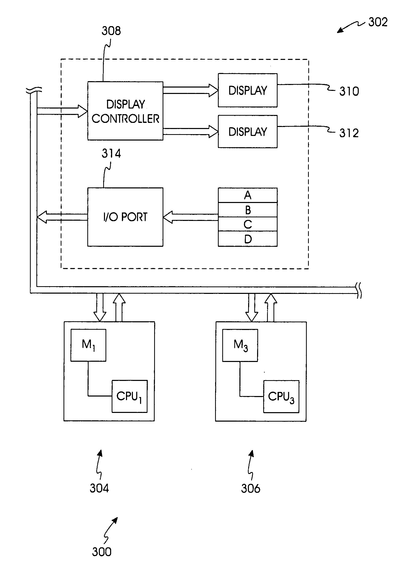
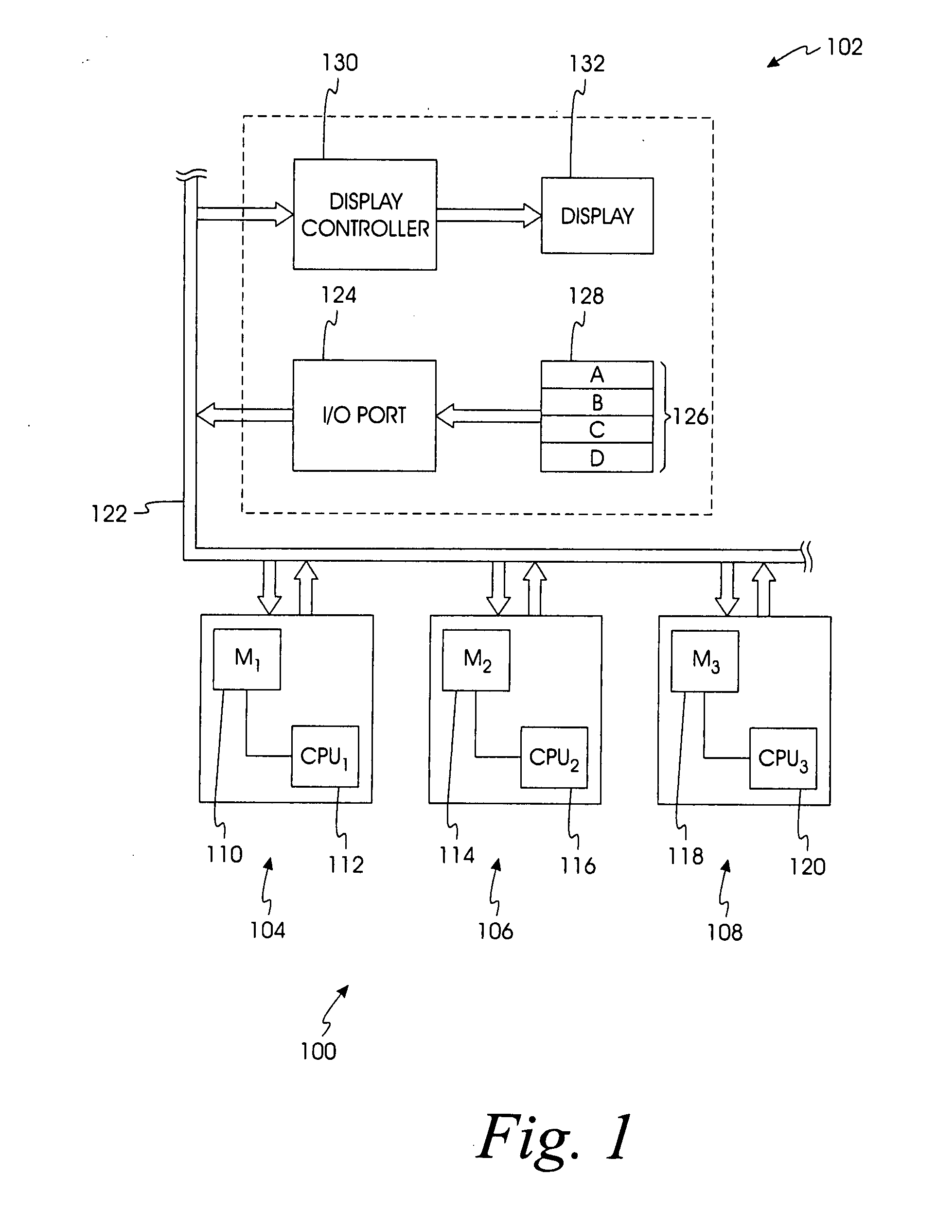
[0019]Turning now to FIG. 1, a block diagram of a remote display chain 100 is generally shown. The remote display chain 100 includes a remote display unit 102, a first metering device 104, a second metering device 106, a third metering device 108, and a serial bus 122. The first metering device 104 includes an electrical meter 110 and a microprocessor 112. The second metering device 106 includes an electrical meter 114 and a microprocessor 116. The third metering device 108 includes an electrical meter 118 and a microprocessor 120.

[0020]As used herein, a metering device refers to any system element or apparatus with the ability to sample, collect, or measure one or more operational characteristics or parameters of a utility system. In this example, the metering devices 104, 106, and 108 can be based on a PowerLogic® Series 3000 / 4000 Circuit Monitor or a PowerLogic® ION7550 / 7650 Power and Energy Meter available from Schneider Electric, or any other suitable monitoring device such as ...


PUM


Abstract

A multi-master serial bus that connects multiple utility monitoring devices with multiple remote electronic display units. The display units include an I2C microprocessor with an integrated LCD controller for controlling an LCD display and a set of buttons for changing what is displayed on the LCD display. They also include an I/O to I2C driver for sending button key presses to the remote monitoring device, which communicates the requested data to be displayed back to the display unit via the multi-master serial bus. Each remote electronic display unit has a unique address assigned to it, and when a user input is detected on the I2C bus by the utility monitoring device, the controller in the utility monitoring device sends monitored data to the detected address for display on the remote electronic display unit.

Description

FIELD OF THE INVENTION[0001]The present invention relates generally to utility monitoring systems and devices and, more particularly, to a power monitoring device that facilitates communication between multiple metering devices and multiple display units.BACKGROUND OF THE INVENTION[0002]Since the introduction of electrical power distribution systems in the late 19th century, there has been a need to monitor their operational and electrical characteristics. The ability to collect, analyze, and respond to information about an electrical power system can improve safety, minimize equipment loss, and ultimately save time and money. To that end, monitoring devices were developed to measure and report such information. These monitoring devices may have a separate user interface for reporting such information from the monitoring device itself. The user interface typically includes a display that is remote from the main monitoring device. The remote display beneficially allows the monitoring...

Claims


Application Information

Patent Timeline
IPC IPC(8): G08C19/00
CPCG01D4/002G06Q50/06Y02B90/246Y04S20/42Y04S20/46Y02B90/241Y04S20/32G01D2204/45G01D2204/18Y02B90/20Y04S20/30
Inventor THURMOND, M.JASONLONG, AVERY D.
Owner SQUARE D CO
Why Eureka
Try Eureka