Three-dimensional light beam acquisition apparatus

a light beam acquisition and three-dimensional technology, applied in the field of three-dimensional light beam acquisition apparatus, can solve the problems of increasing the size of the apparatus, not considering the illumination optical system that irradiates a subject with illumination light, and only performing imaging under predetermined illumination conditions

Inactive Publication Date: 2008-10-02
KK TOSHIBA
View PDF5 Cites 11 Cited by
  • Summary
  • Abstract
  • Description
  • Claims
  • Application Information

AI Technical Summary

Problems solved by technology

However, conventionally no consideration has been given to the illumination optical system that irradiates a subject with illumination light.
Moreover, because the illumination optical system and the imaging optical system, which performs imaging of the subject, are separate, there is a problem of an increased size of an apparatus.
Also, because the illumination conditions, such as an illumination angle and color tone, are fixed, there is a problem that imaging can only be performed under predetermined illumination conditions.

Method used


Image

  • Three-dimensional light beam acquisition apparatus
  • Three-dimensional light beam acquisition apparatus
  • Three-dimensional light beam acquisition apparatus

Examples


second embodiment

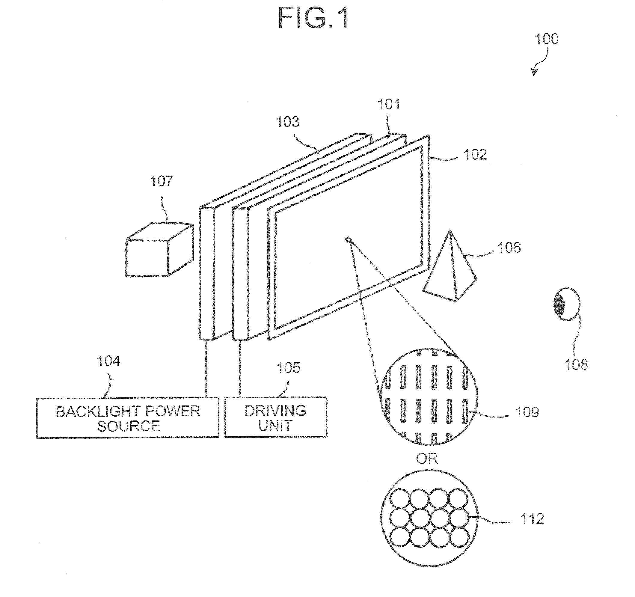
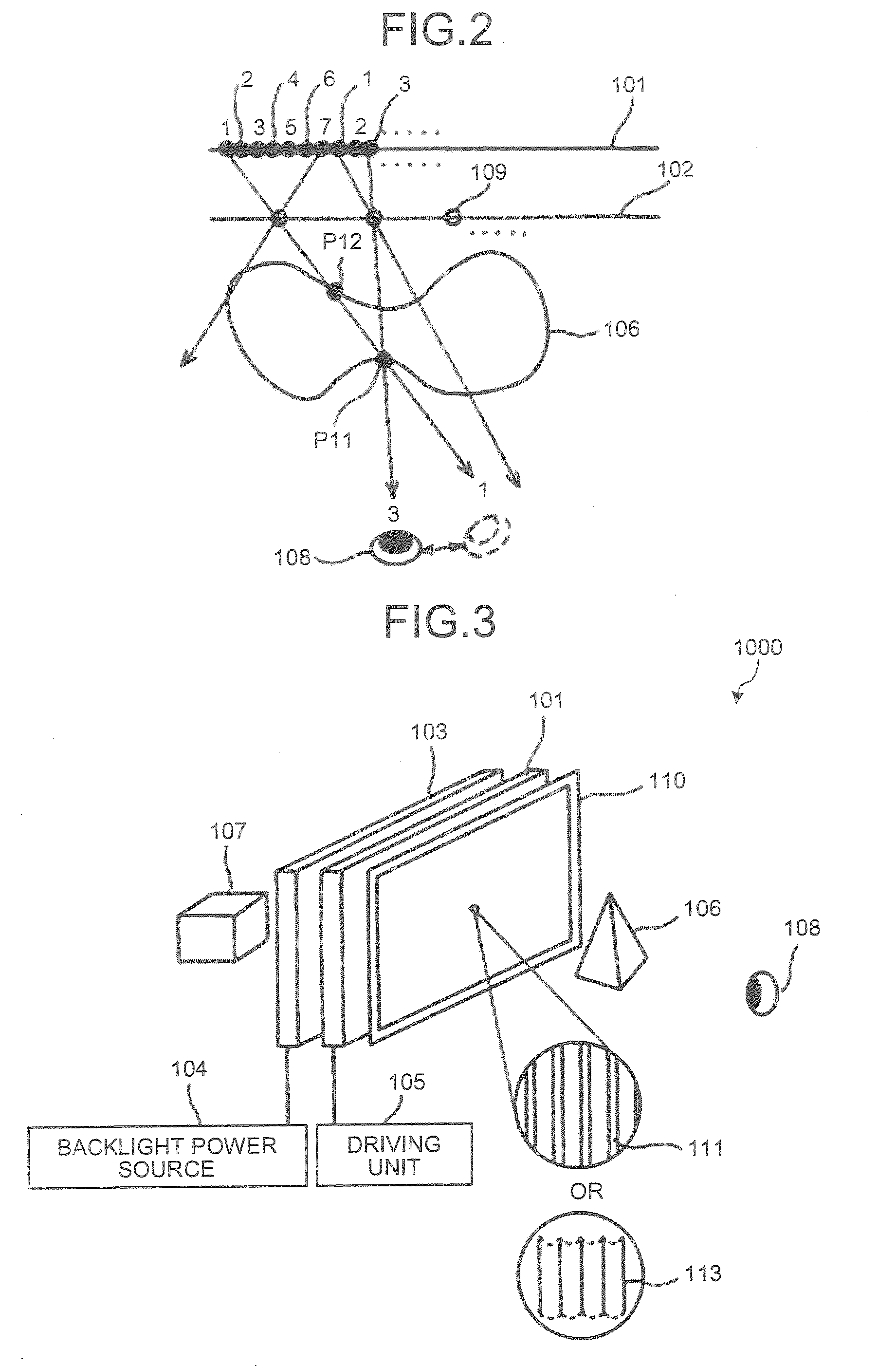
[0057]FIG. 3 is a schematic diagram of a three-dimensional image reproduction apparatus 1000 according to the present invention. In the three-dimensional image reproduction apparatus 1000, a slit array plate 110 is arranged instead of the pinhole array plate 102 shown in FIG. 1. The slit array plate 110 has a plurality of openings, or slits 111, that extend in a vertical direction or a horizontal direction. FIG. 4 is a schematic view of the slit array plate 110 when viewed from front.

[0058]When the slit array plate 110 is used as the light beam control element, parallax in the vertical direction is ignored, because a refractive index in the vertical direction is negligibly small. The slit array plate 110 is advantageous in that it can be manufactured easily than the pinhole array plate 102. Moreover, the slit array plate 110 can reproduce a natural and highly precise three-dimensional image without color separation as the pinhole array plate 102. Instead of the slit array plate 110,...

fourth embodiment

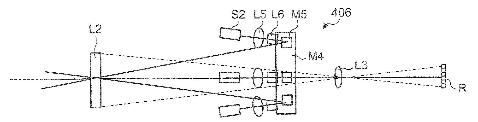
[0087]FIG. 13 is a schematic diagram of an illumination optical system 300 that can be used in the three-dimensional light beam acquisition apparatus 200. The illumination optical system 300 includes a projection lens L4 and a light source S1. Further, the lens L2 and the lens L1 (not shown) of the imaging optical system are used in common as the illumination optical system. In the fourth embodiment, the lens L1 is used. However, it is possible to not use the lens L1 but use only the lens L2 in common as the illumination optical system.

[0088]The projection lens L4 is an optical element that collects light emitted from the light source S1 to a focusing point P1. When the light from the light source S1 is illuminated by the projection lens L4 so as to be collected on one point on the lens L2, the light bends due to the optical characteristics of the lens L2, thereby illuminating the subject through the lens L1. An angle θ11 is an angle at which the light is bent by the lens L2, a foca...

fifth embodiment

[0090]FIG. 14 is a schematic diagram of an illumination optical system 301 according to the present invention. In the illumination optical system 301, a position of the light source S1 is different while the rest of the configuration is the same as that in FIG. 13. When the position of the light source S1 is changed, the focusing point P2 is positioned at a different position from the focusing point P1. In other words, the angle of the illumination light to the subject changes. In this manner, the subject can be illuminated from an arbitrary angle by changing the position of the light source S1.


PUM


Abstract

A three-dimensional light beam acquisition apparatus includes an imaging optical system and an illumination optical system. The imaging optical system includes a first optical element that allows to pass through light from a subject; a second optical element that is arranged on the optical axis of the first optical element, receives the light from the first optical element, and forms an image corresponding to received light; and an acquiring unit that acquires the image from the second optical element as light beam information. The illumination optical system includes a light source; and a third optical element that collects illumination light from the light source and irradiates the subject with the illumination light through the first optical element.

Description

CROSS-REFERENCE TO RELATED APPLICATIONS[0001]This application is based upon and claims the benefit of priority from the prior Japanese Patent Application No. 2007-087386, filed on Mar. 29, 2007; the entire contents of which are incorporated herein by reference.BACKGROUND OF THE INVENTION[0002]1. Field of the Invention[0003]The present invention relates to a three-dimensional light beam acquisition apparatus that acquires light beam information to be displayed on a three-dimensional image reproduction apparatus.[0004]2. Description of the Related Art[0005]A large number of cameras, moving cameras, and the like are used when acquiring three-dimensional light beam information on objects with depth. Various technologies are known that make it possible to acquire such three-dimensional light beam information. For example, in JP-A H11-008863 (KOKAI), a technology that selectively acquires parallel light beams for scanning is disclosed. In JP-A 2003-307800 (KOKAI), to obtain light beam inf...

Claims


Application Information

Patent Timeline
Patent Type & Authority Applications(United States)
IPC IPC(8): H04N13/02G02B30/30H04N13/229H04N13/232H04N13/305H04N13/307
CPCG02B27/2214H04N5/2256H04N13/0207H04N13/0228H04N13/0232H04N13/0253H04N13/0404H04N13/0406H04N13/0409H04N13/0422H04N13/305H04N13/232H04N13/254H04N13/324H04N13/207H04N13/229H04N13/31H04N13/307G02B30/30H04N23/56G02B30/27
Inventor MOMONOI, YOSHIHARUSEKINE, MASAHIRO
Owner KK TOSHIBA
Why Eureka
Try Eureka