Casing mechanism and medical imaging apparatus and ultrasound endoscope using the same

a technology of casing mechanism and endoscope, which is applied in the direction of catheter, coupling device connection, application, etc., can solve the problems of increasing the width of the harness, difficulty in forming the harness and secure the layout space, and the ultrasound signals handled by the ultrasound endoscope apparatus

Active Publication Date: 2008-10-02
OLYMPUS CORP
View PDF20 Cites 4 Cited by
  • Summary
  • Abstract
  • Description
  • Claims
  • Application Information

AI Technical Summary

Benefits of technology

[0041]A casing mechanism according to the present invention includes: a first connector fixedly mounted on a first circuit board; a second connector fixedly mounted on a second circuit board; and stress absorbing means which absorbs stresses produced in the first connector and the second connector when the first circuit board and the second circuit board are fastened to a casing with the first connector and the second connector interconnected.

Problems solved by technology

However, in the case of a medical imaging apparatus such as an ultrasound endoscope apparatus, which has a large number of signal lines extending from a large number (hundreds) of ultrasound transducers and needs to ensure electrical connection of each signal line, the use of harness connection for electrical connection among the circuit boards will result in, for example, increased harness width, which may cause problems such as difficulty to form the harness and secure layout space and susceptibility to ambient noise.
In particular, ultrasound signals handled by the ultrasound endoscope apparatus and the like are weak signals, which are susceptible to noise.
Consequently, with the casing mechanism structured in this way, for example, depending on machining accuracy and the like, there can be misalignment between casing fasteners and board-side fastening locations (screw holes and the like) in the circuit boards which are fastened to the casing fasteners.
In that case, there can also be misalignment between the casing fasteners and board-side fastening locations.
However, with conventional casing mechanisms, it is common that mounting errors are caused by misalignment between circuit boards or between circuit boards and casing fasteners as described above and various measures have been devised by taking this situation into consideration.

Method used


Image

  • Casing mechanism and medical imaging apparatus and ultrasound endoscope using the same
  • Casing mechanism and medical imaging apparatus and ultrasound endoscope using the same
  • Casing mechanism and medical imaging apparatus and ultrasound endoscope using the same

Examples


Embodiment Construction

[0063]The present invention will be described below with reference to an embodiment illustrated in the drawings.

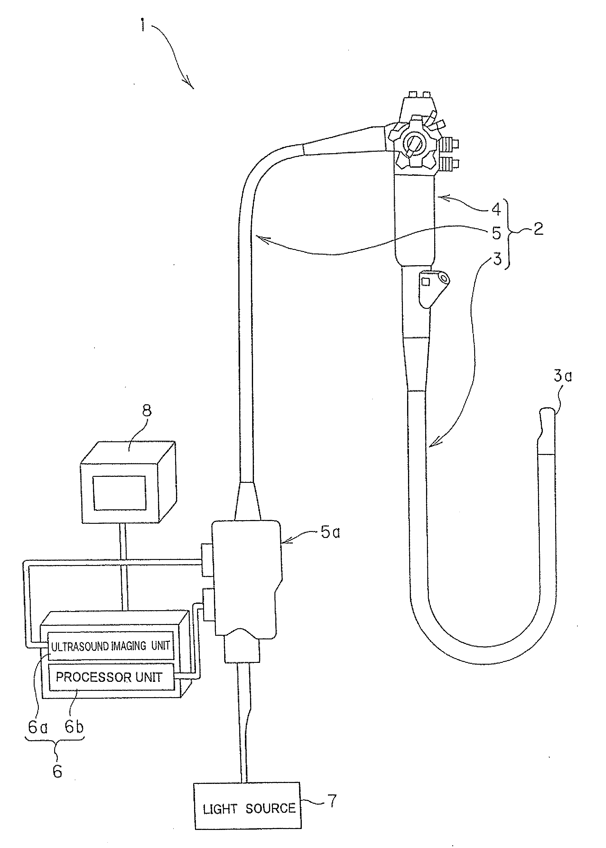
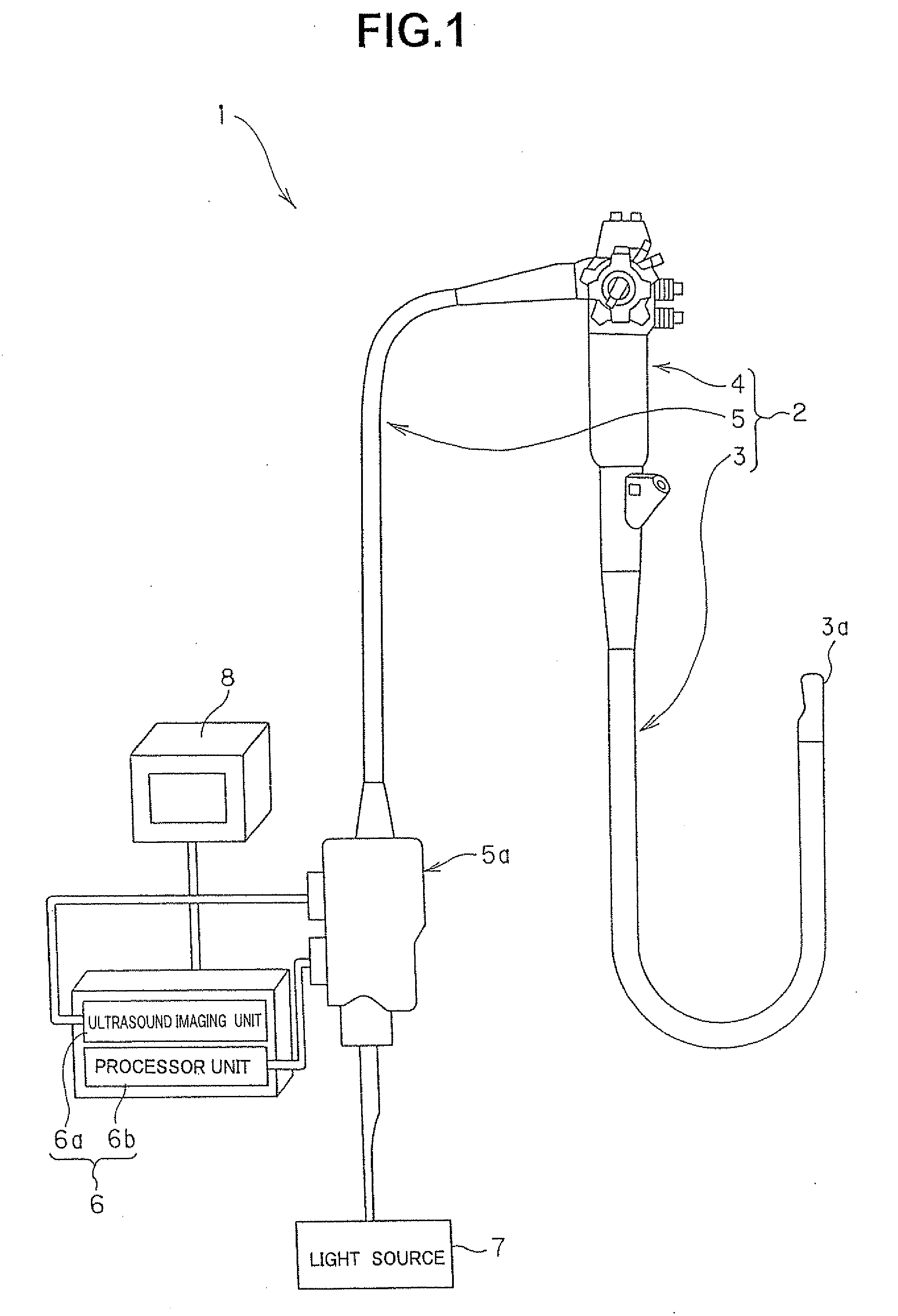
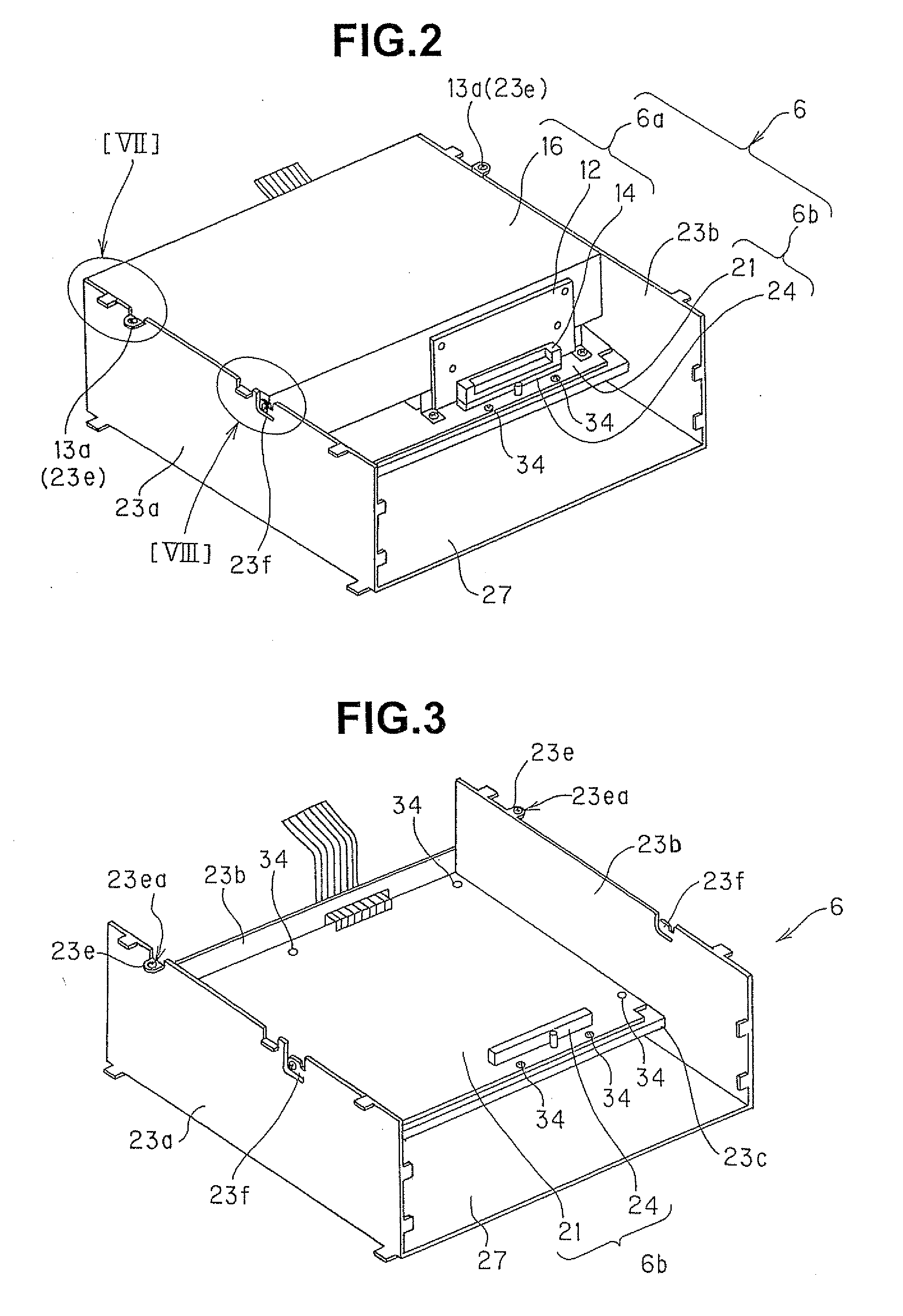
[0064]FIGS. 1 to 8 are diagrams showing an embodiment of the present invention. FIG. 1 is a schematic block diagram outlining an overall configuration of an ultrasound endoscope apparatus which uses a casing mechanism according to the present embodiment. FIG. 2 is an enlarged perspective view showing principal part of a casing mechanism for a controller of the ultrasound endoscope apparatus in FIG. 1. FIG. 3 is a perspective view of a part (processor unit) extracted from an internal configuration of the controller in FIG. 2. FIG. 4 is a perspective view of a part (ultrasound imaging unit) extracted from an internal configuration of the controller in FIG. 2. FIG. 5 is a perspective view showing an internal configuration of the ultrasound imaging unit in FIG. 4 by taking away an outer lid member. FIG. 6 is an enlarged perspective view showing principal part (near a connector...


PUM


Abstract

A casing mechanism according to the present invention includes a first connector fixedly mounted on a first circuit board; a second connector fixedly mounted on a second circuit board; and a stress absorbing member which absorbs stresses produced in the first connector and the second connector when the first circuit board and the second circuit board are fastened to a casing with the first connector and the second connector interconnected.

Description

[0001]This Application claims benefit of Japanese Application No. 2007-094201 filed in Japan on Mar. 30, 2007, the contents of which are incorporated by this reference.BACKGROUND OF THE INVENTION[0002]1. Field of the Invention[0003]The present invention relates to a casing mechanism for electronic equipment and the like as well as to a medical imaging apparatus and ultrasound endoscope using the casing mechanism, where the casing mechanism contains circuit boards, board units, and the like mounted securely in a casing.[0004]2. Description of the Related Art[0005]Medical imaging apparatus such as ultrasound endoscope apparatus equipped with an ultrasound endoscope and the like have been put to practical use, where the ultrasound endoscope and the like is equipped, in a distal end portion of an insertion portion, with an ultrasound transducer which transmits and receives ultrasound waves and an image pickup device such as a photoelectric conversion device so that the insertion portion...

Claims


Application Information

Patent Timeline
Patent Type & Authority Applications(United States)
IPC IPC(8): A61B8/00H05K7/14A61B1/04
CPCA61B8/12H01R13/6315H01R2201/12H05K1/14H05K7/1417H01R12/716Y10S439/928
Inventor KITAHARA, TOSHIHIRO
Owner OLYMPUS CORP
Why Eureka
Try Eureka