
Ultrasonic Endoscope

an endoscope and ultrasonic technology, applied in the field of ultrasonic endoscopes, can solve the problems of spatial loss, increased likelihood of disconnection between the ultrasonic transducer and the connection portion in the fpc board, and the connection portion in the cable and the fpc board, and achieve the effect of shortening the rigid portion required as a space for wiring

Active Publication Date: 2008-08-21
OLYMPUS CORP
View PDF3 Cites 4 Cited by
  • Summary
  • Abstract
  • Description
  • Claims
  • Application Information

AI Technical Summary

Benefits of technology

[0015]In addition, it is another object of the present invention to provide an ultrasonic endoscope in which the length of the rigid portion required as a space for wiring is shortened as much as possible.

Problems solved by technology

The ultrasonic endoscope of the electronic scanning method has the problem that when the FPC boards and the coaxial cables are connected and the components for the cables are inserted into the insertion tube, tensile force applied in the direction of the control section tends to break the connection between the ultrasonic transducer and the FPC boards, which results in disconnection.
Also, because the FPC boards, which are naturally flat shaped, are curved to form an arch, the residual stress of the FPC boards varies with thermal variations and variations in atmospheric pressure during sterilization and disinfection, and the FPC boards tend to change their shape, causing an increased likelihood of disconnection between the ultrasonic transducer and the connection portions in the FPC boards and between the cables and the connection portions in the FPC boards, which is problematic.
Also, the cross section of the FPC board is rectangular while the cross section of the ultrasonic endoscope is circular; accordingly, there is the problem that spatial losses result, requiring larger diameter of the ultrasonic endoscope even when the FPC boards are packed together into the insertion tube.
Also, there is the problem that, because the connection portions are at a place that is closer to the control section than to the bending section, it is difficult to repair when a disconnection is caused in this configuration.

Method used


Image

  • Ultrasonic Endoscope
  • Ultrasonic Endoscope
  • Ultrasonic Endoscope

Examples


Embodiment Construction

[0032]Hereinafter, embodiments of the present invention will be described by referring to the drawings.

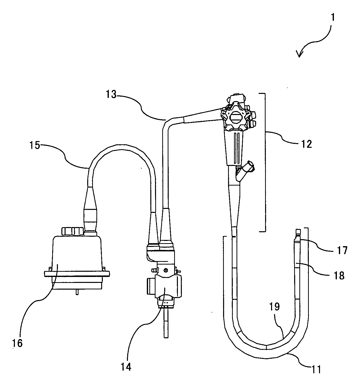
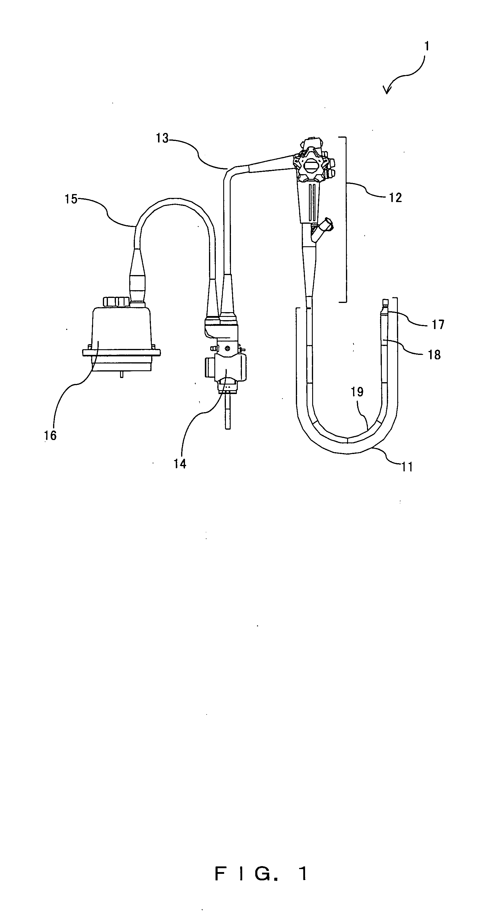
[0033]FIG. 1 shows a configuration of an entire ultrasonic endoscope.

[0034]In FIG. 1, an ultrasonic endoscope 1 comprises an insertion section 11 that is to be inserted into body cavities, a control section 12 connected to a proximal end side of the insertion section 11, and a universal code 13 that extends from a side surface of the control section 12.

[0035]A scope connector 14 that is connected to a light source unit (not shown) for providing illumination light is connected to the proximal end of the universal code 13. An ultrasonic code 15 has an ultrasonic connector 16 that is electrically connected to a diagnostic ultrasound system (not shown) and that is for driving an ultrasonic transducer and creating ultrasonic diagnosis images by performing various signal processes on received signals. The ultrasonic code 15 extends from the scope connector 14.

[0036]The insertion section ...


PUM


Abstract

The present invention provides an ultrasonic endoscope, comprising: an ultrasonic transducer in a cylindrical shape including a plurality of piezoelectric devices, an acoustic matching layer stacked on a principal plane on a sound emitting plane side, an acoustic lens on a plane of the acoustic matching layer opposite to a plane facing the piezoelectric devices, and a backing material stacked on another principal planes of the piezoelectric devices; an endoscopic observation and endo-therapy unit provided, for performing endoscopic image observation, at a proximal end side of the ultrasonic transducer; a cable ass'y including a plurality of cables for transmitting signals to and from the ultrasonic transducer. In the above configuration, the cable ass'y is arranged in such a manner that the cable ass'y passes through an inside portion of the ultrasonic transducer, and is connected to the ultrasonic transducer at a distal end side of the ultrasonic transducer. Thereby, an ultrasonic endoscope is provided that has an ultrasonic transducer in which the ultrasonic transducer and coaxial cables will not be disconnected even under thermal or mechanical loads.

Description

TECHNICAL FIELD [0001]The present invention relates to an electronic radial scanning ultrasonic endoscope, and particularly to a method of connecting coaxial cables for transmitting signals and an ultrasonic transducer in which a plurality of transducer elements are arranged in such a manner that the arranged transducer elements to the cylindrical shape along the periphery of the ultrasonic transducer.BACKGROUND ART [0002]There are two conventional methods of radial scanning ultrasonic endoscopes, the electronic scanning method that performs electronic scans and the mechanical scanning method that performs mechanical scans. In the ultrasonic endoscopes of the electronic scanning method, the configuration is generally employed in which the ultrasonic transducer formed in a cylindrical shape for performing the radial scan and the endoscopic observation and endo-therapy units for performing endoscopic image observation are arranged in very close proximity to each other and are fixed as...

Claims


Application Information

Patent Timeline
Patent Type & Authority Applications(United States)
IPC IPC(8): A61B8/14
CPCA61B8/12B06B1/0633A61B8/4483A61B8/445
Inventor IMAHASHI, TAKUYAMIZUNUMA, AKIKOSAWADA, YUKIHIKOWAKABAYASHI, KATSUHIROSATO, SUNAO
Owner OLYMPUS CORP
Learn More