Balloon catheter with radiopaque marker

a balloon catheter and radiopaque technology, applied in the field of balloon catheters, can solve the problems of increasing the profile of the balloon, increasing affecting the treatment of patients, so as to reduce the rigid length of the balloon, reduce the rigidity of the balloon, and improve the effect of the balloon

Inactive Publication Date: 2012-08-28
ABBOTT LAB INC
View PDF33 Cites 19 Cited by
  • Summary
  • Abstract
  • Description
  • Claims
  • Application Information

AI Technical Summary

Benefits of technology

[0014]The provision of markers being made of a wire of a highly radiopaque and ductile material reduces the rigid length of the markers as the wire provides higher flexibility and also less profile. Therefore, the catheter according to an embodiment of the invention provides a high flexibility and trackability and, simultaneously, the indication of the length of the cylindrical part of the balloon or the length of a stent mounted on the balloon is ensured by the highly radiopaque and ductile material of the wire-markers.
[0015]An embodiment of the catheter according to an embodiment of the invention provides for a wire that is wrapped around the inner tube and preferably at least partly embedded in the tube material. Furthermore, it is possible to build up different kinds of wire arrangements, especially the wire arrangement of a plurality of at least partly overlapping layers that further enhances the radiopacity.

Problems solved by technology

Serious damage results when an area of plaque ruptures and forms a clot, which travels to another part of the body.
If the blood vessels that feed the heart are blocked, a heart attack results.
If the blood vessels to the brain are blocked, a stroke results.
Thus, atherosclerosis can be fatal for some people.
The drawback of these tubes is the increase of profile of the balloon and, even more important, the resulting rigid length of between 1 mm to 1.2 mm which, in turn, results in a reduction in flexibility of the catheter tube.
Therefore, the known catheter, when pushed forward through a curved vessel, suffers from the drawback of an undesired stiffness in the region of the marker bands diminishing especially the trackability of the catheter.
Finally, this stiffening of the catheter tube results in a certain danger of buckling of the catheter.

Method used


Image

  • Balloon catheter with radiopaque marker
  • Balloon catheter with radiopaque marker
  • Balloon catheter with radiopaque marker

Examples


Embodiment Construction

[0023]While this invention may be embodied in many different forms, reference will now be made in detail to specific embodiments of the invention. This description is an exemplification of the principles of the invention and is not intended to limit the invention to the particular embodiments illustrated. For the purposes of this disclosure, like reference numbers in the figures shall refer to like features unless otherwise indicated.

[0024]It will be apparent to those skilled in the art that various modifications and variations can be made to the catheter without departing from the spirit or scope of the invention. Thus, it is intended that the present invention include modifications and variations that are within the scope of the appended claims and their equivalents.

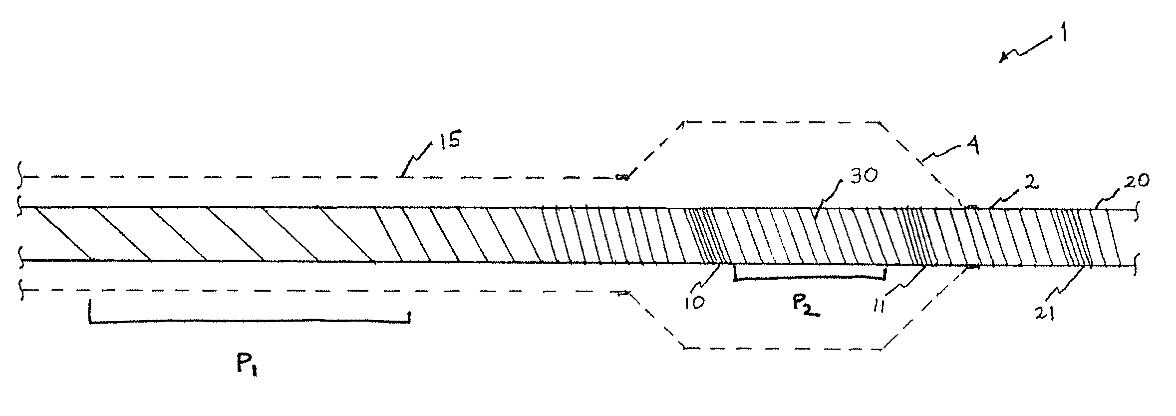
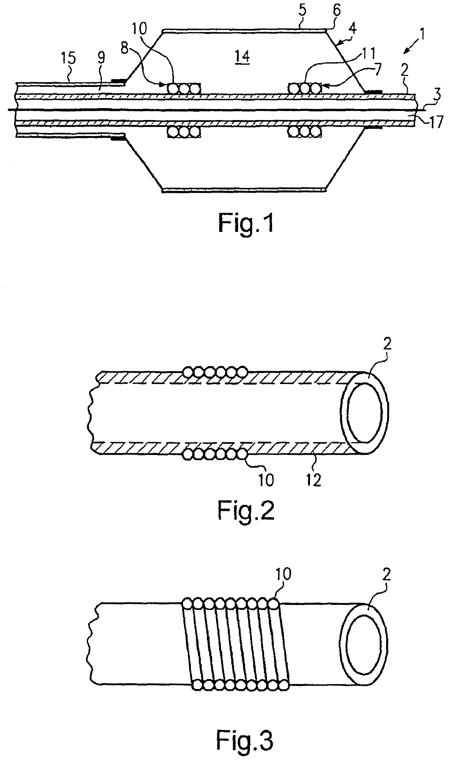
[0025]FIG. 1 depicts a catheter 1 that is particularly adapted for use in delivering a stent 5 disposed on an exterior surface 6 of a balloon 4 of the catheter 1. In accordance with an embodiment of the invention, ball...


PUM


Abstract

A catheter for delivering a stent includes an outer tube having a proximal end, a distal end and a wall defining a lumen; an inner tube disposed within the outer tube and defining a lumen for a guidewire, wherein a portion of a length of the inner tube is wrapped around with a spiral-shaped wire; a balloon sealingly connected to the inner tube and the outer tube adjacent the distal ends thereof, the balloon defining an interior volume and having an exterior surface; and a marker made from a wire of a highly radiopaque and ductile material, wherein the wire is wrapped in a plurality of at least partially overlapping layers such that the marker is flexible along the length of the catheter.

Description

CROSS REFERENCE TO RELATED APPLICATIONS[0001]This application is a continuation-in-part application of U.S. patent application Ser. No. 10 / 523,897 filed Sep. 19, 2005, now U.S. Pat. No. 7,322,959, which is a National stage of PCT / EP03 / 08493, filed Jul. 31, 2003, and which claims priority to EP 02017547.7, filed Aug. 6, 2002, the contents of each of which are incorporated herein by reference.BACKGROUND OF THE INVENTION[0002]1. Field of the Invention[0003]The invention relates to a catheter having a shaft body that incorporates a spiral-shaped radiopaque wire to improve the visibility of the shaft and kink-resistance and push transfer capability of the catheter. Particularly, the invention relates to a catheter for use in delivering a stent which has a radiopaque shaft and exhibits kink resistance.[0004]2. Description of Related Art[0005]Cardiovascular disease is prevalent in the United States and in other parts of the world. One manifestation of cardiovascular disease is atherosclero...

Claims


Application Information

Patent Timeline
Patent Type & Authority Patents(United States)
IPC IPC(8): A61M31/00A61M37/00A61B18/18A61F2/00A61F2/958A61M25/01
CPCA61F2/958A61M25/0108A61F2250/0098A61M2025/1079
Inventor WARNACK, BORIS
Owner ABBOTT LAB INC
Why Eureka
Try Eureka