Puncture needle device for ultrasonic endoscope

a needle device and ultrasonic technology, applied in the field of puncture needle devices for ultrasonic endoscopes, can solve the problems that the puncture needle device cannot stand against, and achieve the effects of improving the operability of the puncture needle device, facilitating lock member operation, and enhancing the force preventing the cylindrical connecting body from tilting relative to the pipe sleev

Active Publication Date: 2013-08-20
HOYA CORP
View PDF7 Cites 5 Cited by
  • Summary
  • Abstract
  • Description
  • Claims
  • Application Information

AI Technical Summary

Benefits of technology

[0011]According to an aspect of the present invention, a puncture needle device is provided, detachably attached to an ultrasonic endoscope via a pipe sleeve which projects from the ultrasonic endoscope, the pipe sleeve including a non-circular-shaped collar, the puncture needle device including a cylindrical connecting body into which the pipe sleeve is inserted when the puncture needle device is attached to the ultrasonic endoscope, the cylindrical connecting body including an insertion limit portion which comes in contact with the pipe sleeve to prevent the pipe sleeve from being further inserted into the cylindrical connecting body when the pipe sleeve is inserted into the cylindrical connecting body to a predetermined position in an internal space of the cylindrical connecting body; and a non-circular-shaped collar receiving hole which is engaged with the collar and irrotatable relative to the collar when the pipe sleeve is inserted into the cylindrical connecting body to the predetermined position; a flexible sheath which projects outwardly from the cylindrical connecting body through the internal space thereof and is inserted into an internal conduit of the ultrasonic endoscope through the inside of the pipe sleeve when the pipe sleeve is inserted into the internal space of the cylindrical connecting body; a puncture needle inserted into the sheath to be movable therein; and a lock member supported by the cylindrical connecting body to be movable between an unlocked position that allows the pipe sleeve to be inserted into the cylindrical connecting body to the predetermined position and to be removed from the cylindrical connecting body, and a locked position wherein the lock member contacts the collar of the pipe sleeve, that is inserted into the cylindrical connecting body to the predetermined position, to thereby prevent the collar from moving in a removal direction from the cylindrical connecting body.
[0028]It is desirable for the surface in the collar receiving hole and the pipe sleeve to be made of a same metallic material. Accordingly, the abrasion resistance of the surface in the collar receiving hole can further be improved, and hence, further reducing the possibility of wear.

Problems solved by technology

However, if a large torque is exerted on the puncture needle device, the puncture needle device cannot stand against this large torque solely by the aforementioned frictional resistance, thus the puncture needle device freely rotates about the central axis thereof.

Method used


Image

  • Puncture needle device for ultrasonic endoscope
  • Puncture needle device for ultrasonic endoscope
  • Puncture needle device for ultrasonic endoscope

Examples


first embodiment

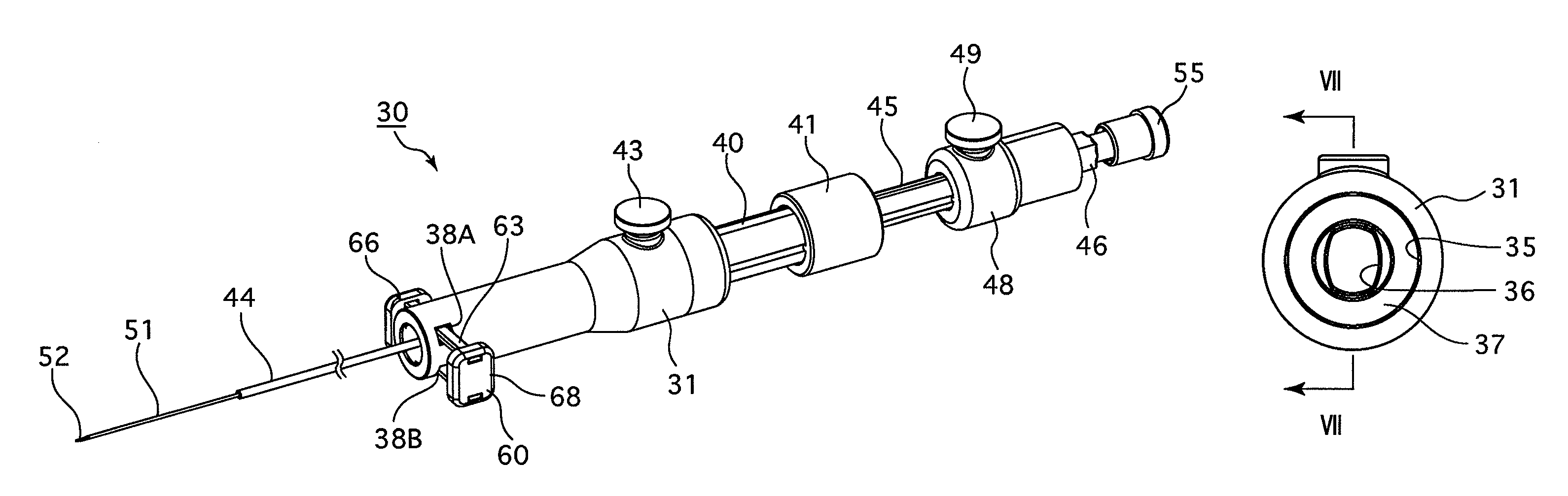
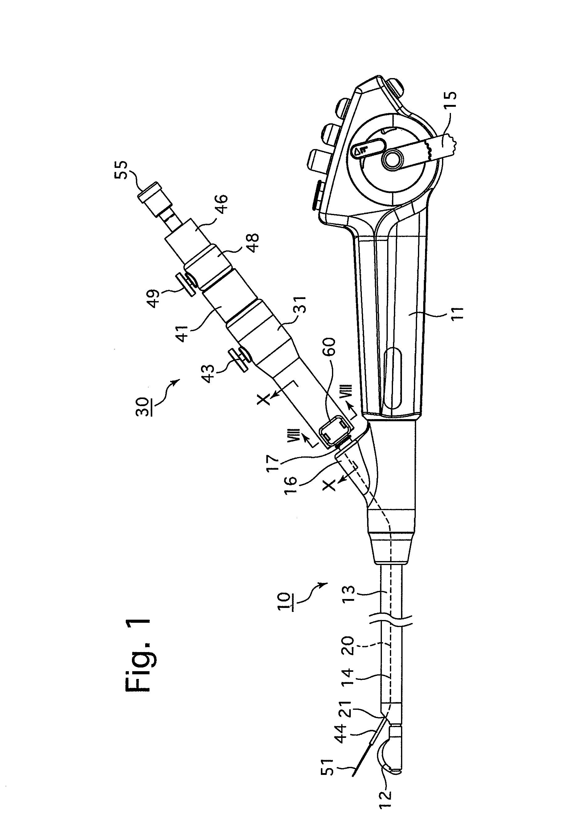
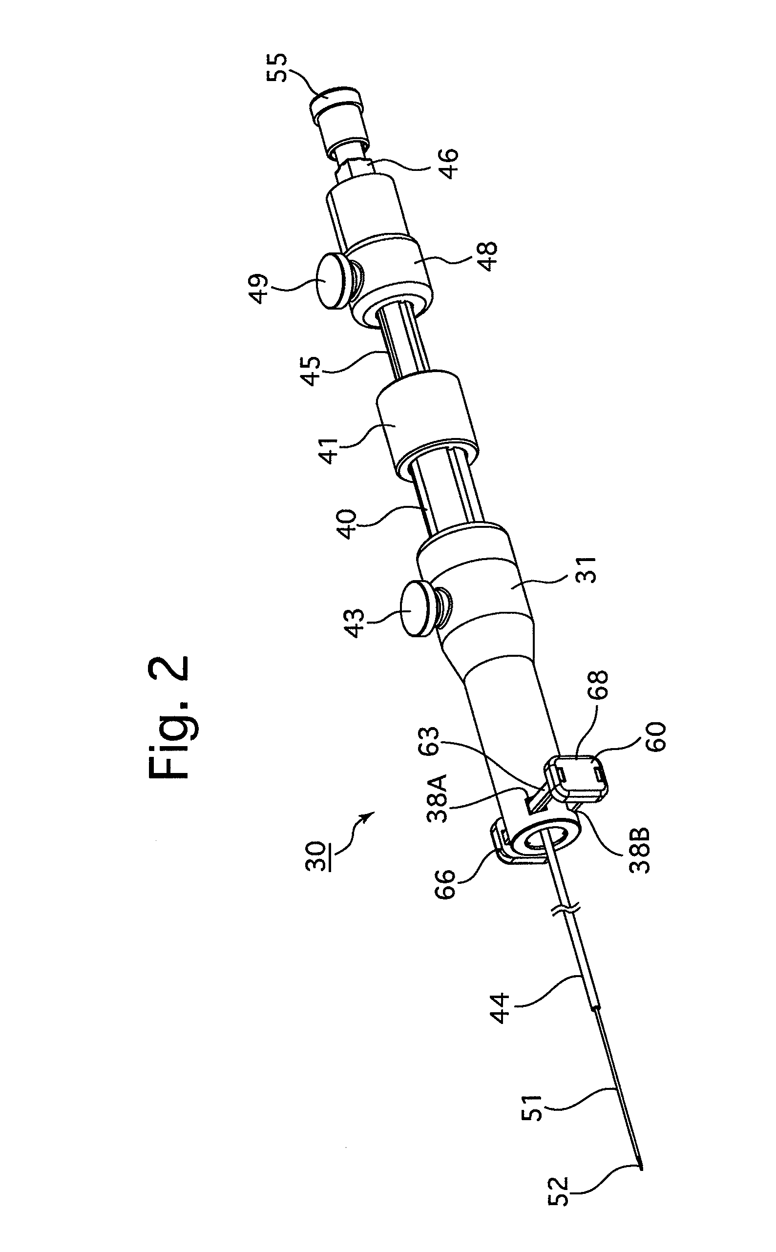
[0061]a puncture needle device for ultrasonic endoscope according to the present invention will be hereinafter discussed with reference to FIGS. 1 through 11. In the following descriptions, the distal-end side of an insertion portion 13 is defined as the front side of an ultrasonic endoscope 10 and a control body 11 side is defined as the rear side of an ultrasonic endoscope 10. Additionally, in a puncture needle device 30, the tip of a puncture needle (centesis needle) 51 is defined as the front side of the puncture needle device 30 and a stylet support cap 55 side is defined as the rear side of the puncture needle device 30.

[0062]Firstly, the structure of the ultrasonic endoscope 10 to which the puncture needle device 30 can be detachably attached will be discussed hereinafter.

[0063]The ultrasonic endoscope 10 is provided with the control body 11, the insertion portion 13, a light guide tube (not shown) and an ultrasonic image transmission tube (not shown). The insertion portion 1...

second embodiment

[0080]The structure of a puncture needle device 70 will be discussed hereinafter.

[0081]The puncture needle device 70 is provided with a cylindrical connecting body 71 which is in the shape of a substantially circular cylinder and made of the same material as the cylindrical connecting body 31. A slider support hole 32 is formed through the cylindrical connecting body 71 except a front internal portion thereof, and a female screw hole 33 (not shown in FIGS. 12 through 16), through which the slider support hole 32 and the outer space of the cylindrical connecting body 71 are communicatively connected to each other, is formed as a through-hole in a rear portion of the cylindrical connecting body 71. The cylindrical connecting body 71 is provided at the front end thereof with an annular recess 72 which is recessed rearward and shaped into a ring as viewed from the front. A female thread 73 is formed on the inner peripheral surface of the annular recess 72. A collar receiving hole 36 is...

third embodiment

[0095]As described above, in the puncture needle device also, the puncture needle device 70 can be made immovable relative to the pipe sleeve 17.

[0096]In addition, upon the operator (user) releasing his / her hand from the lock member 60 after mounting the puncture needle device 70 to the pipe sleeve 17, the lock member 60 automatically slides to the locked position, which yields an improvement in connection operability of the puncture needle device 70 with the pipe sleeve 17. In addition, the puncture needle device 70 can be prevented from coming off the pipe sleeve 17 when the operator forgets to move the lock member 60 to the locked position.

[0097]Moreover, even in the case where an external force urging the lock member 60 to move toward the unlocked position is unexpectedly applied to the lock member 60, the lock member 60 is held in the locked position by the pair of compression coil springs S1, so that the locked state of the puncture needle device 70 by the lock member 60 is ef...


PUM


Abstract

A puncture needle device detachably attached to an ultrasonic endoscope via a pipe sleeve including a non-circular collar, including a cylindrical connecting body into which the pipe sleeve is inserted, the cylindrical connecting body including an insertion limit portion which contacts the pipe sleeve to prevent it from being further inserted, and a non-circular collar receiving hole engaged with the collar and irrotatable relative thereto when the pipe sleeve is inserted; a sheath projecting from the cylindrical connecting body and inserted into an internal conduit of the ultrasonic endoscope; a puncture needle inserted into the sheath; and a lock member supported by the cylindrical connecting body and movable between an unlocked position allowing the pipe sleeve to insert and remove from the cylindrical connecting body, and a locked position wherein the lock member contacts the collar of the pipe sleeve to prevent it from removing from the cylindrical connecting body.

Description

BACKGROUND OF THE INVENTION[0001]1. Field of the Invention[0002]The present invention relates to a puncture needle device for ultrasonic endoscope which is used while being inserted into an internal conduit of an ultrasonic endoscope.[0003]2. Description of the Related Art[0004]An ultrasonic endoscope with a pipe sleeve projecting from a control body of the ultrasonic endoscope, and a puncture needle device detachably attached to the pipe sleeve are disclosed in Japanese Unexamined Patent Publication 2005-137814.[0005]This puncture needle device includes a cylindrical connecting body of the puncture needle device, a sheath which projects outwardly through an internal space of the cylindrical connecting body, and a puncture needle which is inserted into the sheath to be movable therein.[0006]When the puncture needle device is used, an end of a cylindrical forceps plug, made of an elastic material such as rubber, is mounted to the pipe sleeve with the aid of the elasticity of the elas...

Claims


Application Information

Patent Timeline
Patent Type & Authority Patents(United States)
IPC IPC(8): A61B17/34
CPCA61B8/12A61B17/3478A61B2017/00477A61B2017/3413A61B1/00137A61B1/00133A61B1/018A61B1/00128
Inventor SATO, MASAYASUFUJITA, YASUNOBUTARUMOTO, TETSUYA
Owner HOYA CORP
Why Eureka
Try Eureka