
Electronic data shift device, in particular for coding/decoding with an LDPC code

a data shifter and data technology, applied in the field of data shifters, can solve the problems of complex routing problems, inability to meet the requirements of the inability of barrel shifters to offer a satisfactory approach to hardware flexibility and reconfigurability

Inactive Publication Date: 2008-10-02
STMICROELECTRONICS SRL
View PDF7 Cites 13 Cited by
  • Summary
  • Abstract
  • Description
  • Claims
  • Application Information

AI Technical Summary

Benefits of technology

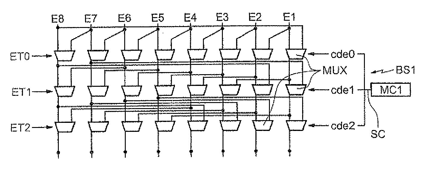
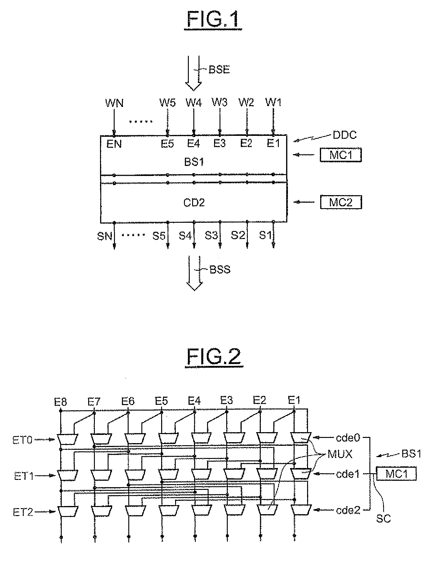
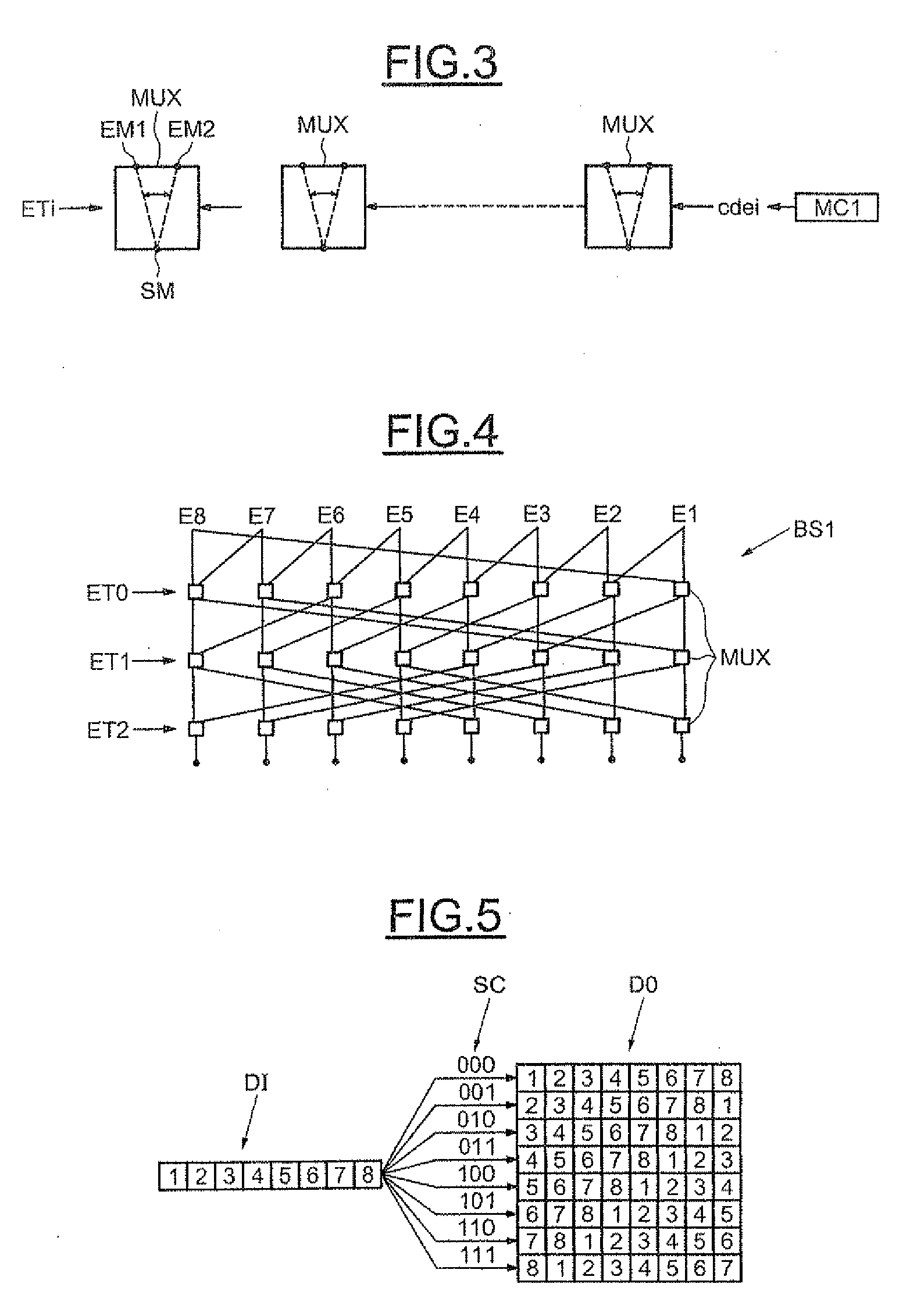
[0004]According to one embodiment, a shift device is proposed that offers a certain flexibility as to the number of input data that can be received and with a surface area that is smaller than an approach providing for the use of several barrel shifters of different sizes. According to one aspect, an electronic shift device is proposed, comprising a configurable barrel shifter connected between the inputs and the outputs of the device and a first controller or means to configure the barrel shifter according to the desired shift value.
[0016]For example, the shift stage associated with a predetermined intermediate size value p comprises p−1 multiplexing means that can be controlled separately, each multiplexing means having a first input connected to an input of the device, an output connected to the input of the barrel shifter having the same rank as the input of the device and a second input connected to another input of the device. Each multiplexing means has a first state in which its output is connected to its second input and a second state in which its output is connected to its first input, and at least one multiplexing means is in its first state when the shift stage is in its first state, all the multiplexing means of the stage are in their second state when the shift stage is in its second state and at least some of the multiplexing means are in their second state when the shift stage is in its third state. Whatever the placement of the second shifter relative to the barrel shifter, the second control means are advantageously able to control separately each multiplexing means of a shift stage according to the desired shift value.

Problems solved by technology

This may pose a problem when there is a need to connect another circuit downstream of the barrel shifter.
Also, it can immediately be seen that these barrel shifters may not offer a satisfactory approach to the hardware flexibility and reconfigurability mentioned above and required to satisfy the emergence of different standards, except, of course, by using as many barrel shifters as there are bus sizes to be envisaged, involving an appropriate selection device, or even a single barrel shifter having the maximum size with, downstream, a complex wire routing device configurable according to the actual size of the input data bus.
Now, these two approaches may cover a relatively large surface area and / or may pose complex routing problems.

Method used


Image

  • Electronic data shift device, in particular for coding/decoding with an LDPC code
  • Electronic data shift device, in particular for coding/decoding with an LDPC code
  • Electronic data shift device, in particular for coding/decoding with an LDPC code

Examples


Embodiment Construction

[0033]In FIG. 1 the reference DDC denotes an electronic shift device comprising N inputs E1-EN and N outputs S1-SN. The device DDC is able to receive data Wi originating from an input bus BSE, and deliver shifted data on an output bus BSS. As will be seen in more detail below, the organization of these data that can actually be received as input to the device DDC can be different and is chosen from a certain number of predetermined organizations.

[0034]Thus, for example, the device DDC can simultaneously receive N data W1-WN organized, for example, in a single group, or even a group of data with a size greater than 1 and less than N and chosen from certain predetermined sizes. The input data can also be organized in several groups received simultaneously as input to the device DDC. In other words, the device DDC is here a multimode device in as much as it is capable of handling the case of a bus BSE of size N, that is, simultaneously receiving N data as input, or even the case of a b...


PUM


Abstract

The electronic shift device includes N inputs and N outputs, a configurable barrel shifter connected between the N inputs and the N outputs. A second shifter is arranged and connected between some of the outputs of the barrel shifter and some of the N outputs according to different predetermined organizations of data that can be received simultaneously on at least some of the N inputs. The second shifter is configurable so that, for a relevant organization and regardless of the desired shift value compatible with the organization, the corresponding input data are delivered to predetermined outputs. A first controller is able to configure the barrel shifter according to the desired shift value and a second controller is able to configure the second shifter according to the organization of the data that can actually be received and according to the desired shift value.

Description

FIELD OF THE INVENTION[0001]The invention relates to data shift devices which may be used to perform a cyclical permutation of the input data. Such devices are, for example, but not exclusively, used in channel coding devices including encoders using codes based on blocks with a parity matrix that has a low density and are more widely known to those skilled in the art as an “LDPC code” (“Low Density Parity Check”), or in channel decoding devices including LDPC decoders, or in devices using turbocodes to perform a part of the data interleaving.BACKGROUND OF THE INVENTION[0002]LDPC codes are proposed for numerous standards (e.g. 802.11n, 802.16e, DVB-S2, etc.). The emergence of these numerous standards requires these data shift devices to be flexible and reconfigurable in hardware terms. Conventional data shift devices are commonly known to those skilled in the art as barrel shifters. These barrel shifters are based on a logarithmic architecture of multiplexers and, when they are of s...

Claims


Application Information

Patent Timeline
Patent Type & Authority Applications(United States)
IPC IPC(8): G06F5/01
CPCG06F5/015G06F7/762H03M13/1137H03M13/116H03M13/6519H03M13/6527H03M13/6544
Inventor PAUMIER, LAURENTHEINRICH, VINCENT
Owner STMICROELECTRONICS SRL
Learn More