Beam for a drywall ceiling soffit

a technology for ceiling soffits and beams, applied in ceilings, walls, flooring, etc., can solve problems such as parts not fitting well together

Active Publication Date: 2008-10-09
WORTHINGTON ARMSTRONG VENTURE
View PDF10 Cites 22 Cited by
  • Summary
  • Abstract
  • Description
  • Claims
  • Application Information

AI Technical Summary

Benefits of technology

[0016]The invention permits beams to be rapidly and uniformly bent, and fixed, to form a desired angle, in the field, to create a framework for a ceiling soffit.

Problems solved by technology

Such work in the field is time-consuming, and often non-uniform, so that the parts do not fit well together.

Method used


Image

  • Beam for a drywall ceiling soffit
  • Beam for a drywall ceiling soffit
  • Beam for a drywall ceiling soffit

Examples


Embodiment Construction

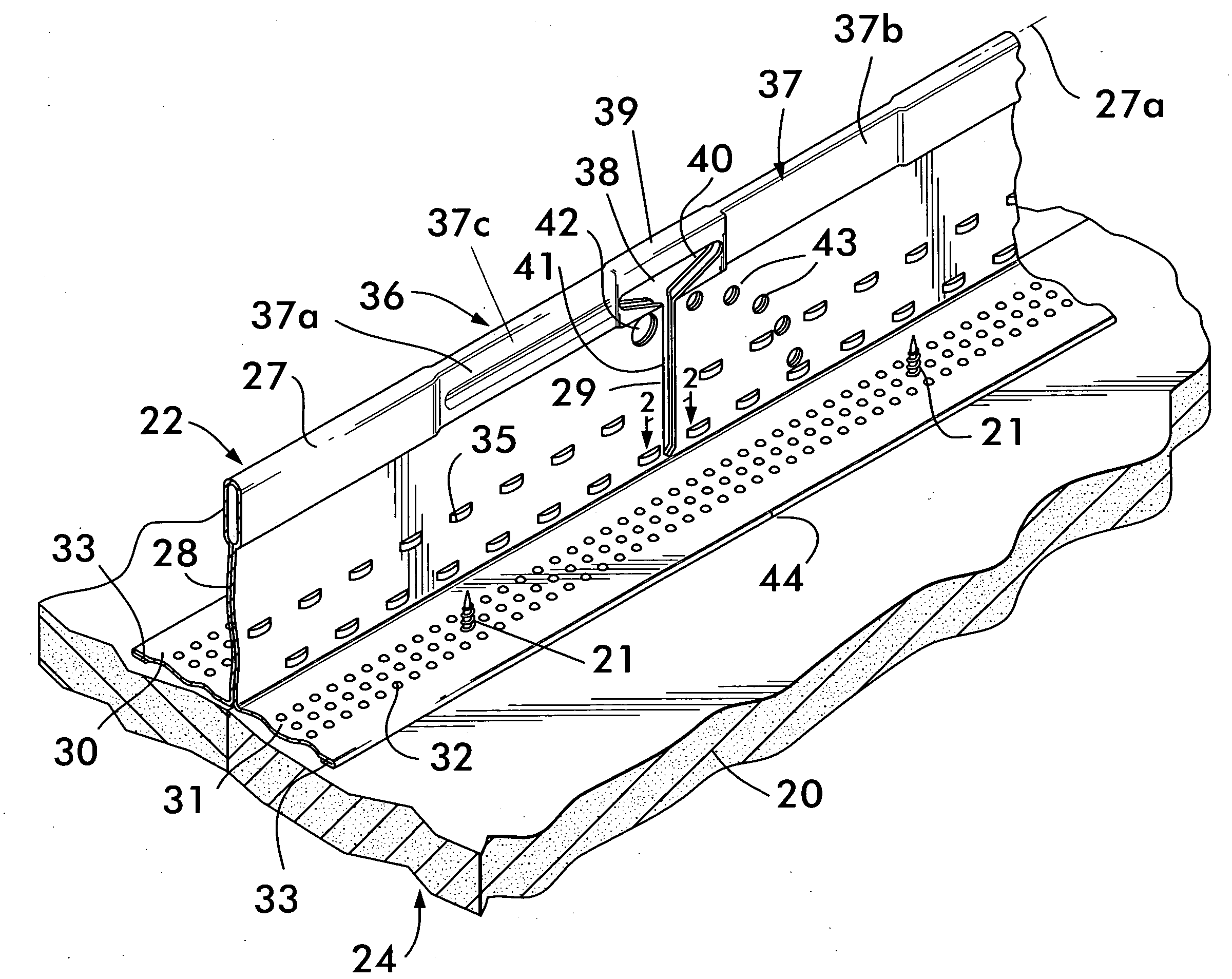
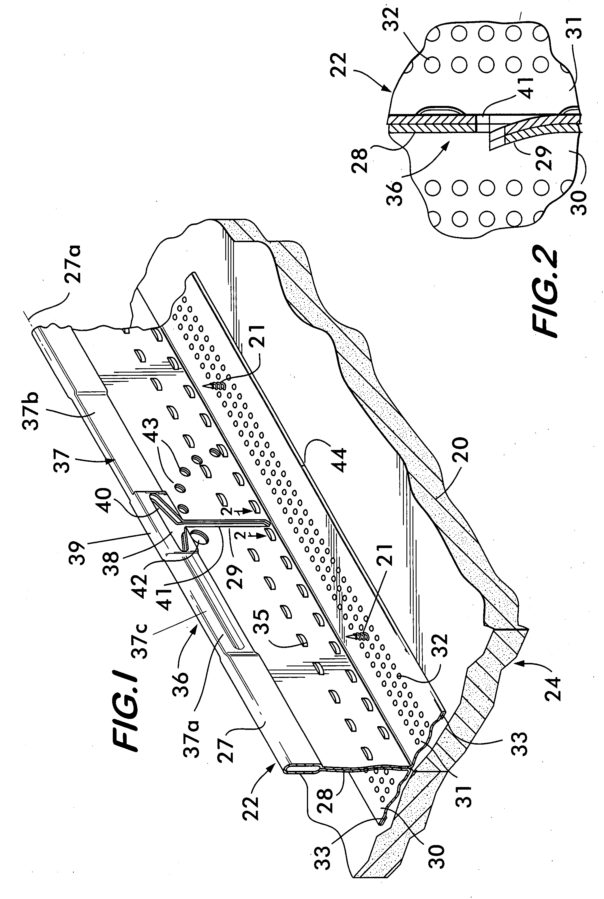
[0034]The invention will be disclosed as applied to the beam in the '098 patent, although the invention is suited for other prior art rollformed beams that support ceiling drywall.

[0035]As seen particularly in FIG. 1, drywall 20, in sheet form, is affixed by self-tapping screws 21 to beam 22 in a framework of beams that support the drywall 20, to form a horizontal suspended drywall ceiling 24. In a horizontal suspended drywall ceiling 24, such beams 22 are interlocked into a grid supported from a structural ceiling by hanger wires.

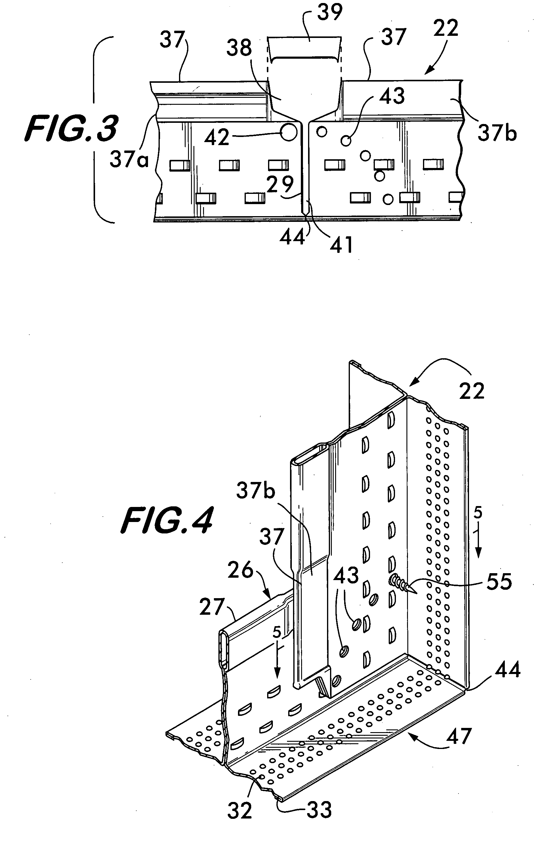
[0036]In some instances, a plurality of beams 22 is used to form a framework for a ceiling soffit 23. Examples of such ceiling soffits 23 are seen in FIGS. 10, 11, and 14 wherein the framework of beams 22 is suspended by hanger wires 25, as seen in FIGS. 10 and 14, or by the beams 22 themselves, as seen in FIG. 11.

[0037]The present invention is concerned with the bends 26 in the beams 22 that are necessary in forming the ceiling soffit 23. A horizontal sus...


PUM


Abstract

A straight rollformed beam made for use in a suspended horizontal drywall ceiling is modified so that it can be used in a drywall ceiling underhang known as a drywall ceiling soffit.
The beam is made with repetitive configurations along the length of the beam that are selectively cut, in the field, so that the beam can be bent to, and then fixed at, a desired angle.
Drywall panels are secured to a plurality of such beams that form a framework for the soffit.

Description

BACKGROUND OF THE INVENTION[0001](1) Field of the Invention[0002]The invention relates to beams that support attached drywall sheets to form suspended drywall ceilings and ceiling soffits.[0003](2) Description of the Related Art[0004]Beams used in suspended drywall ceilings are well known. In such ceilings, beams are suspended by hanger wires from a structural ceiling, and sheets of drywall are secured to the suspended beams by self-tapping screws.[0005]The beams are made by continuously rollforming a strip of metal to fold the strip longitudinally into an inverted T cross section, with a bulb at the top, a web extending down from the bulb, and two flanges extending horizontally opposite from one another at the lower end of the web. The flanges have indentations over their lower surface that capture self-tapping screws to permit the screws to penetrate the flange after passing through the drywall sheet.[0006]Such a beam is shown, for instance, in U.S. Pat. No. 6,722,098, for Beam fo...

Claims


Application Information

Patent Timeline
Patent Type & Authority Applications(United States)
IPC IPC(8): E04B9/06
CPCE04B9/061E04B9/068
Inventor MILLER, DONALD C.PLATT, WILLIAM J.
Owner WORTHINGTON ARMSTRONG VENTURE
Why Eureka
Try Eureka