
Pen injector having a needle shield

a needle shield and injector technology, applied in the direction of intravenous devices, infusion needles, infusion syringes, etc., can solve the problem of accidental needle sticks

Inactive Publication Date: 2008-10-09
WEST PHARM SERVICES INC
View PDF22 Cites 42 Cited by
  • Summary
  • Abstract
  • Description
  • Claims
  • Application Information

AI Technical Summary

Benefits of technology

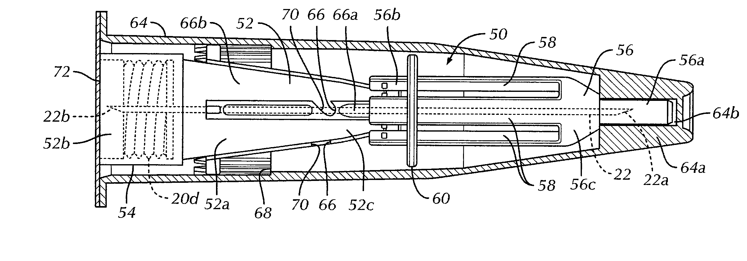
The present invention is about a pen injector that has a vial cartridge and a tubular body with a mounting end and a driving end. The needle shield assembly is removably mounted to the mounting end of the body and includes a hollow needle with a tip for injecting into a patient. A slideable sleeve is slideably mounted on the needle hub and has a receiving end and an injection end. The needle hub has an outer surface that deflects the slideable sleeve as it moves between the extended and retracted positions. The slideable sleeve bears resiliently on the outer surface of the needle hub during sliding movement. This results in a restoring force that pushes the slideable sleeve to move towards the injection end of the needle hub and into the extended position. The invention also includes a knob for setting a dosage level and driving the piston in accordance with the set dosage level. The needle shield assembly is designed to protect the needle from damage during storage and use. The technical effects of the invention are improved safety and ease of use for patients and healthcare professionals.

Problems solved by technology

Diabetics and others frequently find themselves in situations where the assistance of a health professional to administer subcutaneous or intra muscular injections of measured amounts of a liquid agent is generally not available.
Though a removable cap is usually included, accidental needle sticks can occur when the needle is not in use or when replacing cap on the needle.

Method used


Image

  • Pen injector having a needle shield
  • Pen injector having a needle shield
  • Pen injector having a needle shield

Examples


Embodiment Construction

[0021]Certain terminology is used in the following description for convenience only and is not limiting. The words “right”, “left”, “lower” and “upper” designate directions in the drawings to which reference is made. The words “inwardly” and “outwardly” refer to directions toward and away from, respectively, the geometric center of a pen injector having a needle shield in accordance with the present invention, and designated parts thereof. Unless specifically set forth herein, the terms “a”, “an” and “the” are not limited to one element but instead should be read as meaning “at least one”. The terminology includes the words noted above, derivatives thereof and words of similar import.

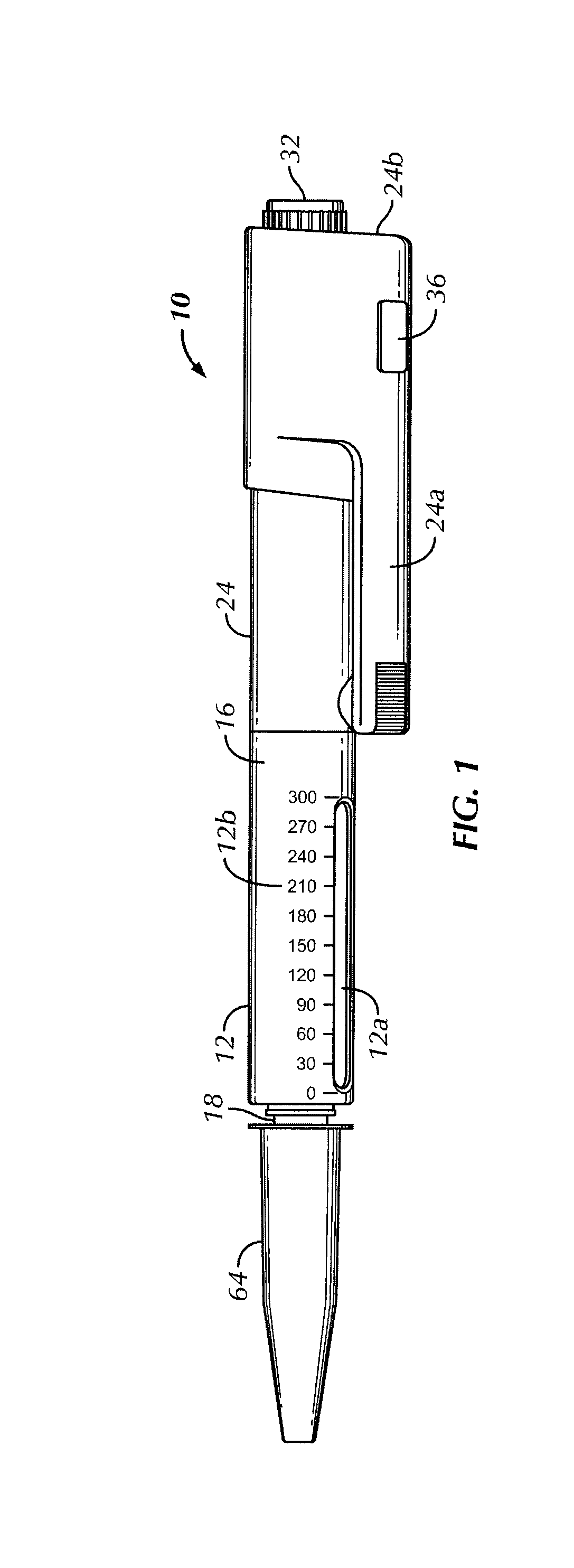
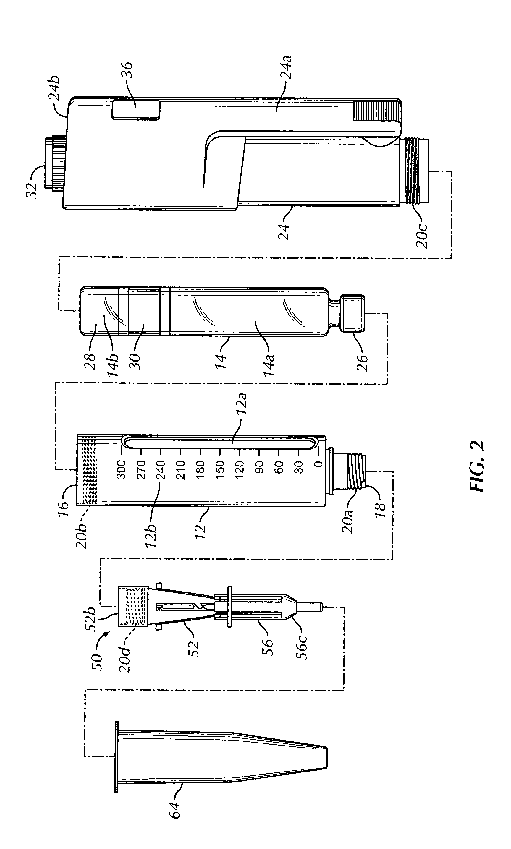
[0022]Referring to the drawings in detail, wherein like reference numerals indicate like elements throughout, there is shown in FIGS. 1-4H a preferred embodiment of a pen applicator or injector, generally designated 10, having a needle shield assembly 50 in accordance with the present invention. As show...


PUM


Abstract

A pen injector includes a vial cartridge and a generally tubular body that surrounds the vial cartridge. A needle shield assembly is removably mounted to a mounting end of the body and includes a hollow needle that has a tip for injecting into a patient. A needle hub at least partially surrounds the hollow needle and a slideable sleeve is slideably mounted on the needle hub. The needle hub has an outer surface which deflects the slideable sleeve as the slideable sleeve slides toward a receiving end of the needle hub and into a retracted position. The slideable sleeve bears resiliently on the outer surface of the needle hub during sliding movement of the slideable sleeve relative to the needle hub toward the retracted position such that a restoring force is generated for urging the slideable sleeve to move toward an injection end of the needle hub and into an extended position in which the tip of the needle is located completely inside of the slideable sleeve.

Description

CROSS-REFERENCE TO RELATED APPLICATIONS[0001]This application claims the benefit of U.S. Provisional Patent Application No. 60 / 910,331 filed Apr. 5, 2007 entitled “Pen Applicator with Needle Shield” which is incorporated by reference herein in its entirety.BACKGROUND OF THE INVENTION[0002]The present invention relates to the incorporation of a passive needle protection system for needles used with pen type medical injection systems (pen injectors).[0003]Diabetics and others frequently find themselves in situations where the assistance of a health professional to administer subcutaneous or intra muscular injections of measured amounts of a liquid agent is generally not available. In such situations such persons need to have a low cost syringe which does not require the assistance of a healthcare professional for an injection to achieve the desired measure of accuracy. It is often the case that such persons require more than one dose per day, each dose being of different volumes. Disp...

Claims


Application Information

Patent Timeline
Patent Type & Authority Applications(United States)
IPC IPC(8): A61M5/32
CPCA61M5/24A61M5/326A61M5/3271A61M2005/3267A61M2005/3268
Inventor PAPROSKI, JOHNNORTON, PAUL
Owner WEST PHARM SERVICES INC
Learn More