Interface assembly for controlling orientation of robotically controlled medical instrument

a robotic control and interface technology, applied in the field of surgical instruments, can solve the problems of long recovery time, visible scarring, and significant pain of surgery utilizing conventional procedures

Inactive Publication Date: 2008-10-09
HANSEN MEDICAL INC
View PDF51 Cites 1058 Cited by
  • Summary
  • Abstract
  • Description
  • Claims
  • Application Information

AI Technical Summary

Problems solved by technology

Traditionally, surgery utilizing conventional procedures meant significant pain, long recovery times, lengthy work absences, and visible scarring.

Method used


Image

  • Interface assembly for controlling orientation of robotically controlled medical instrument
  • Interface assembly for controlling orientation of robotically controlled medical instrument
  • Interface assembly for controlling orientation of robotically controlled medical instrument

Examples


Embodiment Construction

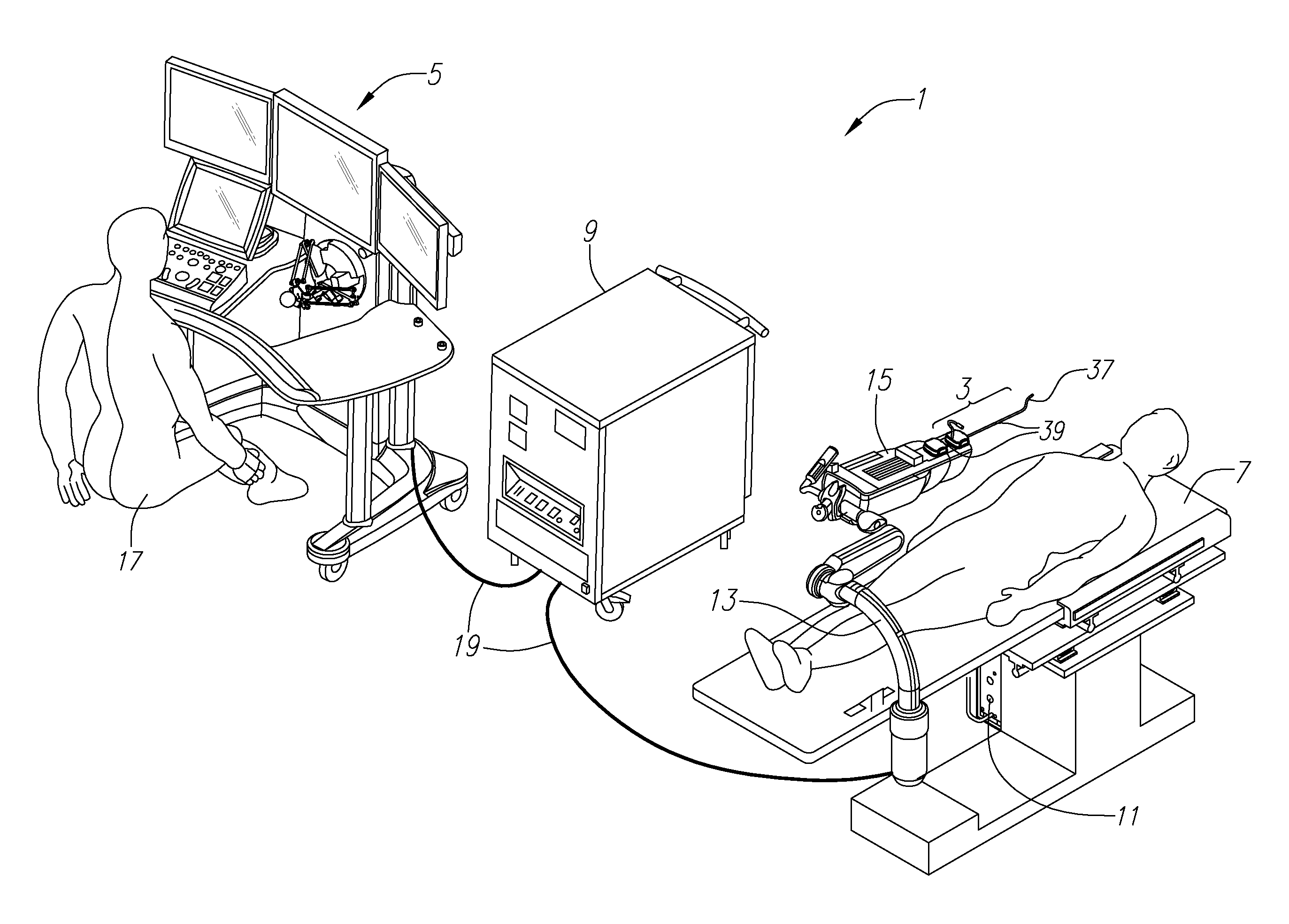
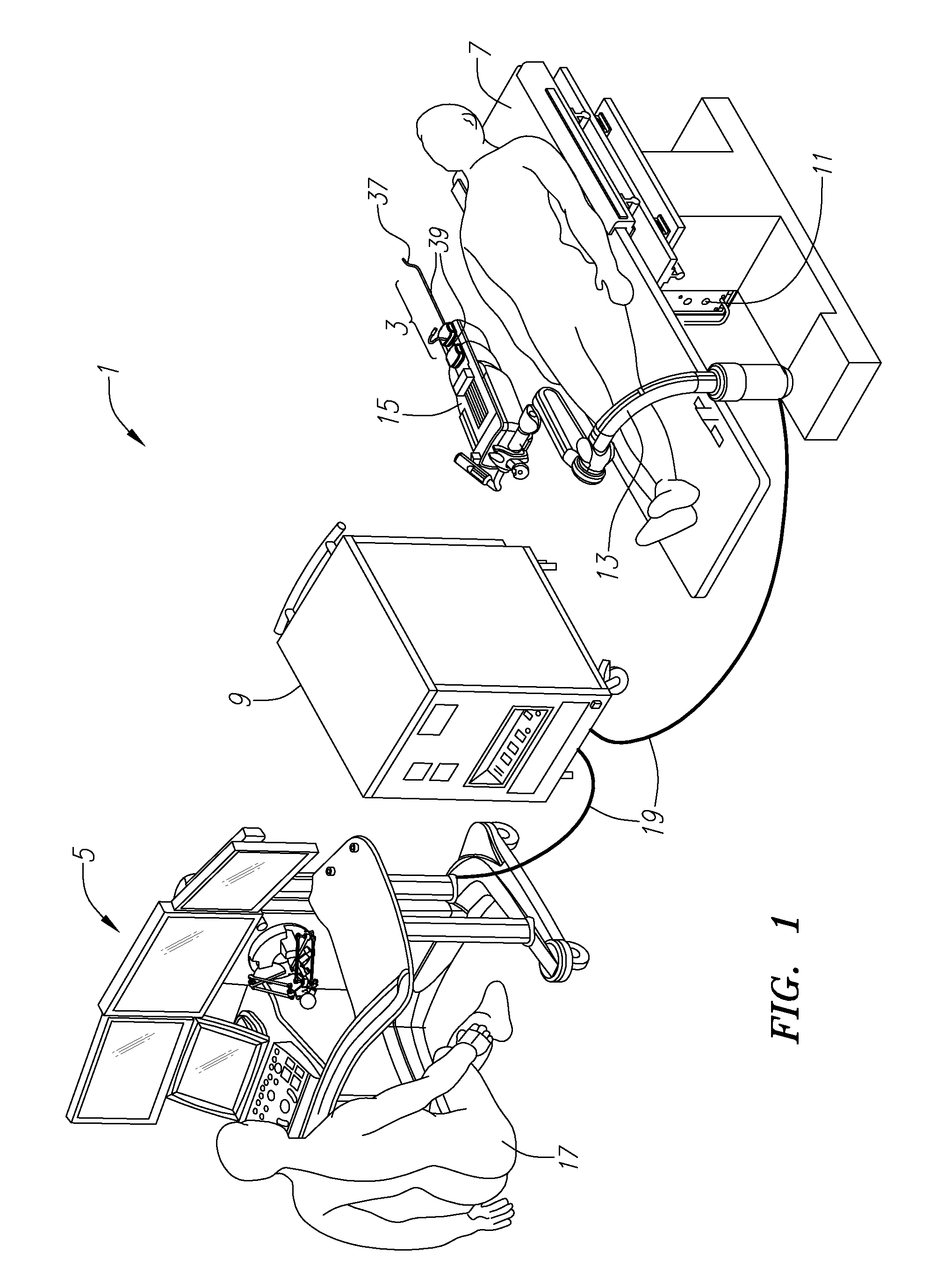
[0079]Embodiments of the present invention are directed to controlling a flexible distal portion or tip of a catheter or catheter assembly and mechanisms for controlling and orienting distal tip shapes and movement. Although embodiments are described in the context of robotically controlled catheters, embodiments may also be utilized with or applied to other types of surgical devices including, but not limited to, endoscopes and laparoscopes. Embodiments may thus be described with reference to various instruments including an “instrument member”, a “flexible member”, a “flexible instrument”, a “catheter”, a “catheter member”, a “flexible catheter instrument”, a “catheter assembly” and the like, which may, in some cases, be identified by different reference numbers in different embodiments / figures, but which are generally the same or substantially similar devices that include an elongated tubular member having a controllable distal working end that may carry one or more working instr...


PUM


Abstract

Interface assemblies for controlling an orientation of a working instrument of a robotic medical instrument system. A base member is coupled to a distal end of an instrument such as a robotically controllable catheter. A spacer element is retained between the base member and a platform member, which is movable relative to the base member about the spacer element. One or more control elements extending through a base member aperture can be used to control an orientation of the platform member and working instrument.

Description

CROSS-REFERENCE TO RELATED APPLICATIONS[0001]The present application claims the benefit under 35 U.S.C. §119 to U.S. Provisional Application No. 60 / 902,144, filed on Feb. 15, 2007, the contents of which are incorporated herein by reference as though set forth in full.[0002]The present application may also be related to subject matter disclosed in the following applications and patents, the contents of which are also incorporated herein by reference as though set forth in full: U.S. patent application Ser. No. 10 / 923,660, entitled “System and Method for 3-D Imaging”, filed Aug. 20, 2004; U.S. patent application Ser. No. 10 / 949,032, entitled “Balloon Visualization for Transversing a Tissue Wall”, filed Sep. 24, 2005; U.S. patent application Ser. No. 11 / 073,363, entitled “Robotic Catheter System”, filed Mar. 4, 2005; U.S. patent application Ser. No. 11 / 173,812, entitled “Support Assembly for Robotic Catheter Assembly”, filed Jul. 1, 2005; U.S. patent application Ser. No. 11 / 176,954, en...

Claims


Application Information

Patent Timeline
Patent Type & Authority Applications(United States)
IPC IPC(8): A61B19/00
CPCA61B19/2203A61B2017/003A61B2019/2211A61B2019/2223A61B2019/2238A61B2019/2242A61B2019/2273A61B2019/5261A61M25/0113A61B34/30A61B34/37A61B34/71A61B2034/2061A61B2034/301A61B2034/306A61B2034/741
Inventor STAHLER, GREGORY J.WALLACE, DANIEL T.SALISBURY, J. KENNETH
Owner HANSEN MEDICAL INC
Why Eureka
Try Eureka