Eureka AIR delivers breakthrough ideas for toughest innovation challenges, trusted by R&D personnel around the world.

Cooling module applied for liquid containers

Inactive Publication Date: 2008-10-16
YEN SUN TECH CORP
View PDF5 Cites 7 Cited by
  • Summary
  • Abstract
  • Description
  • Claims
  • Application Information

AI Technical Summary

Benefits of technology

[0007]The primary objective of this invention is to provide a cooling module applied for liquid containers. The cooling pipeline and liquid pipeline both are embedded and installed inside the thermal-exchanging matrix, and the thermal-exchanging matrix is pre-cooled, being kept at a predetermined temperature “a” by means of the thermal sensor and the thermal controller. Consequently, a greatly improved thermal exchanging efficiency and low energy loss of the liquid is fulfilled.
[0008]The secondary objective of this invention is to provide a cooling module applied for liquid containers. The cooling pipeline and liquid pipeline are installed and embedded inside the thermal exchanging matrix respectively and never contact or connect to each other anyway being free from a refrigerant leakage and therefore not polluted the liquid inside the cooling pipeline. This results in a great liquid quality and safety for drinking.
[0009]Another objective of this invention is to provide a cooling module applied for liquid containers. The cooling pipeline and liquid pipeline are entirely wrapped up inside the thermal exchanging matrix respectively. Accordingly, the cooling pipeline and the liquid pipeline can't make thermal exchanging with the atmosphere in a way directly. Consequently, a greatly improved thermal exchanging efficiency and low energy loss of the liquid is achieved.
[0010]The beverage heating method in accordance with an aspect of the present invention includes a cooling pipeline, a liquid pipeline, a thermal-exchanging matrix, a thermal sensor and a thermal controller. A cooling pipeline, formed with an inlet and an outlet for refrigerants to flow through. A liquid pipeline conducts liquids to flow through the thermal-exchanging matrix. The thermal-exchanging matrix is made from metals with high thermal conductivities, installed and embedded inside the thermal-exchanging matrix the cooling pipeline and liquid pipeline both. The thermal sensor is attached upon an outer circumference of the thermal-exchanging matrix. The thermal controller is electrically connected to the thermal sensor. Consequently, the liquids is cooled down by which flow through the thermal-exchanging matrix in short time by means of the thermal sensor to monitor and keep the temperature of the thermal-exchanging matrix for absorbing the thermal energy of the liquid.

Problems solved by technology

Accordingly, the cooling pipeline and the liquid pipeline can't make thermal exchanging with the atmosphere in a way directly.

Method used


Image

  • Cooling module applied for liquid containers
  • Cooling module applied for liquid containers
  • Cooling module applied for liquid containers

Examples


Embodiment Construction

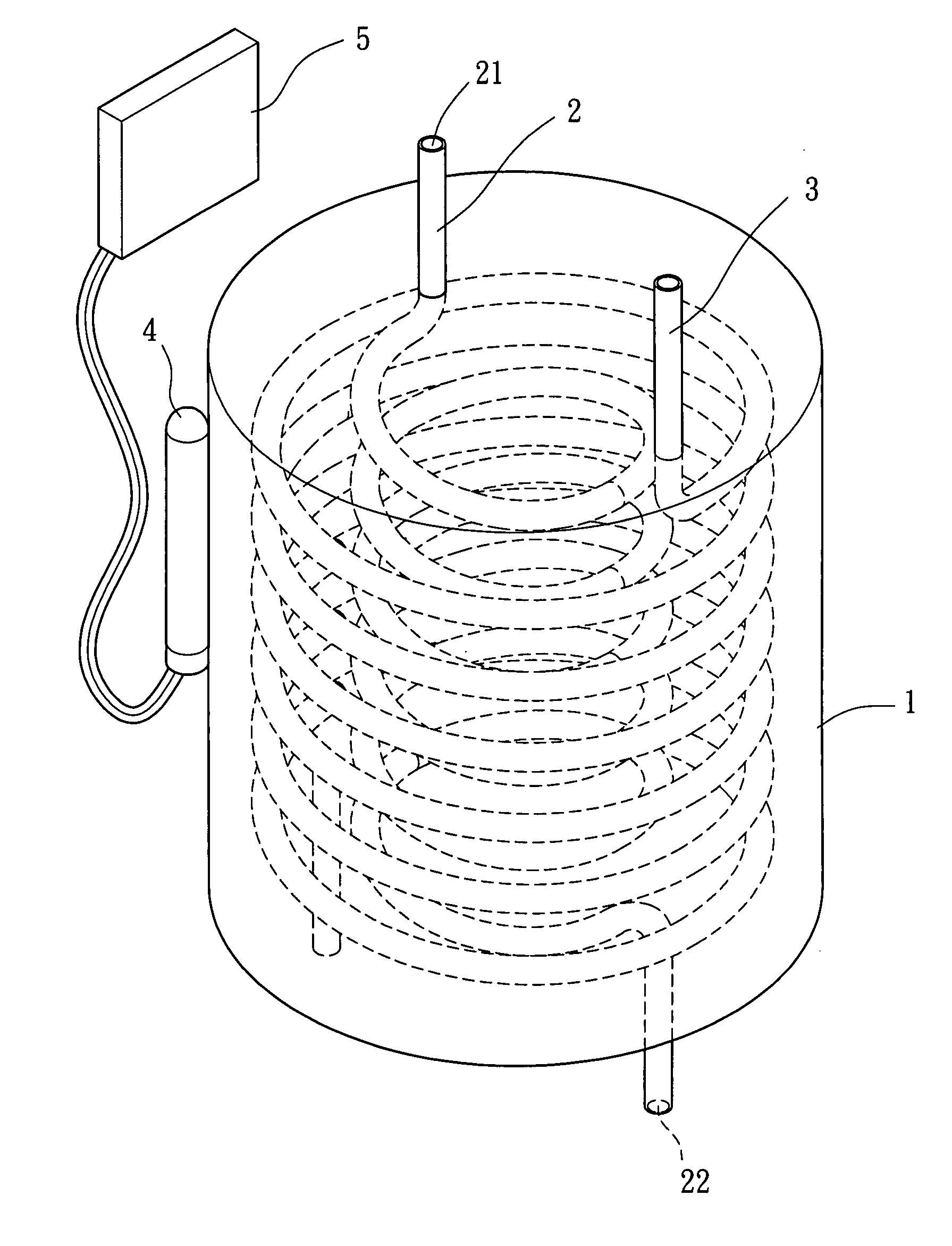
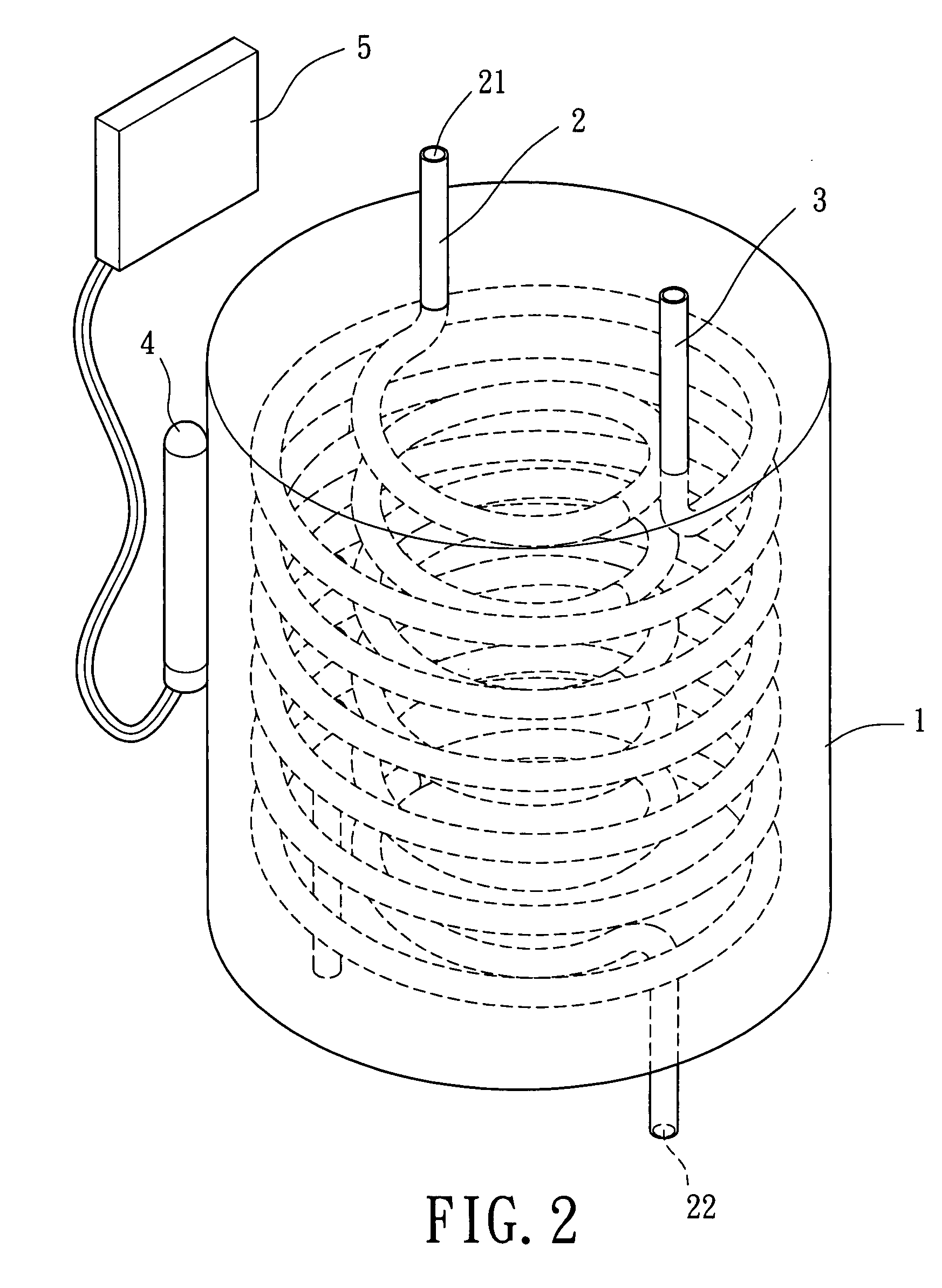
[0017]Referring now to FIG. 2 and 3, The cooling module applied for liquid containers in accordance with a first embodiment of the present invention is preferably applied for a cool beverage dispenser or cool drink dispenser, however, it can be further applied for various thermal exchanging apparatus, and details omitted herein.

[0018]Referring again to FIG. 2 and 3, the cooling module applied for liquid containers in accordance with a first embodiment of the present invention includes a thermal-exchanging matrix 1, a cooling pipeline 2, a liquid pipeline 3, a thermal sensor 4 and a thermal controller 5. The thermal-exchanging matrix 1 is made from materials with high thermal conductivities (for example: copper, aluminum or alloys thereof). The figure of the thermal-exchanging matrix 1 in cross-sectional view can be a circle, rectangular or others. The cooling pipeline 2 and liquid pipeline 3 both install inside the thermal-exchanging matrix 1. The thermal sensor 4 contacts with the ...


PUM


Abstract

A cooling module applied for liquid containers comprises: A cooling pipeline forms with an inlet and an outlet for refrigerant to flow through. The liquid pipeline conducts liquids to flow through a thermal-exchanging matrix. The thermal-exchanging matrix is made from metals such as copper or aluminum. The cooling pipeline and liquid pipeline are both installed inside the thermal-exchanging matrix. The thermal-exchanging matrix is pre-cooled and therefore being kept at a predetermined temperature by the thermal controller. Consequently, through flown in and out of the thermal-exchanging matrix, the liquid is cooled down in short time and therefore kept at the predetermined temperature.

Description

BACKGROUND OF THE INVENTION[0001]1. Field of the Invention[0002]The present invention relates to a cooling module applied for liquid containers. More particularly, the present invention relates to pre-cool a thermal-exchanging matrix at a predetermined temperature so that the thermal energy of the liquid is absorbed into the thermal-exchanging matrix in short time. Consequently, the cooling efficiency of the liquid is improved.[0003]2. Description of the Related Art[0004]As can be seen in FIG. 1, a conventional cooling module applied for liquids includes a thermal-exchanging pipeline 7, an inlet joint 8, and an outlet joint 9. One end of the thermal-exchanging pipeline 7 connects to the inlet joint 8, and the other end of the thermal-exchanging pipeline 7 connects to the outlet joint 9. The thermal-exchanging pipeline 7 equips with an inner pipeline 71 and an outer pipeline 72, thereby, the inner pipeline 71 inside the outer pipeline 72 to commonly constitute the thermal-exchanging ...

Claims


Application Information

Patent Timeline
IPC IPC(8): B67D5/00B67D99/00
CPCB67D1/0862F25B2700/21F25D31/002F28D7/0008
Inventor CHEN, CHIEN-JUNG
Owner YEN SUN TECH CORP
Why Eureka
Eureka Blog
Learn More