Synchronized vacuum belt feeder

Active Publication Date: 2008-10-16
OSI MACHINERIE
View PDF6 Cites 3 Cited by
  • Summary
  • Abstract
  • Description
  • Claims
  • Application Information

AI Technical Summary

Benefits of technology

[0008]There if provided a vacuum belt feeder for transferring items from a supply zone to a discharge zone, comprising a means of conveyance provided with suction heads connected to vacuum chambers, the suction heads being continuously actuated under vacuum, wherein pickup of the items in the supply zone and release of the items at target locations in the d

Problems solved by technology

However, in cases where the transferred items must be sorted out in relation to classification criteria, it is not sufficient that the ite

Method used


Image

  • Synchronized vacuum belt feeder
  • Synchronized vacuum belt feeder
  • Synchronized vacuum belt feeder

Examples


Embodiment Construction

[0016]The present invention will now be described, for illustrative purposes only, in relation to the wood floor manufacturing industry, although it may be used in other fields, as will become more apparent upon reading the following.

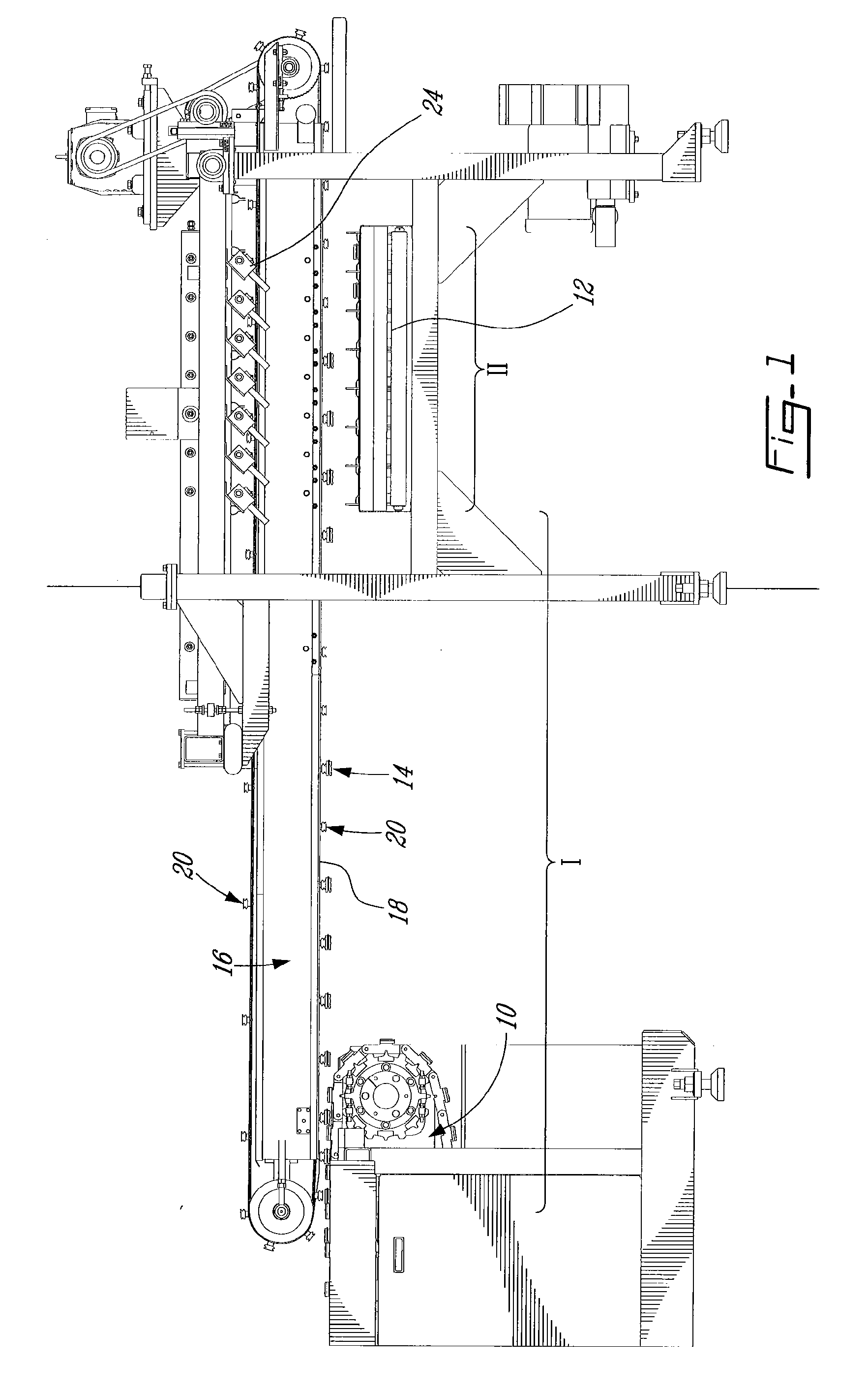
[0017]As illustrated in FIG. 1 of the appended drawings, for exemplary purposes only, a wood floor manufacturing system generally comprises a tenoner 10 and conveyor units 16 and 12 to a wood grader (not shown). The tenoner 10 generally machinates boards 14. At the output of the tenoner 10, the conveyor unit 16 conveys the items 14 from the tenoner 10 to the conveyor unit 12 leading to the wood grader.

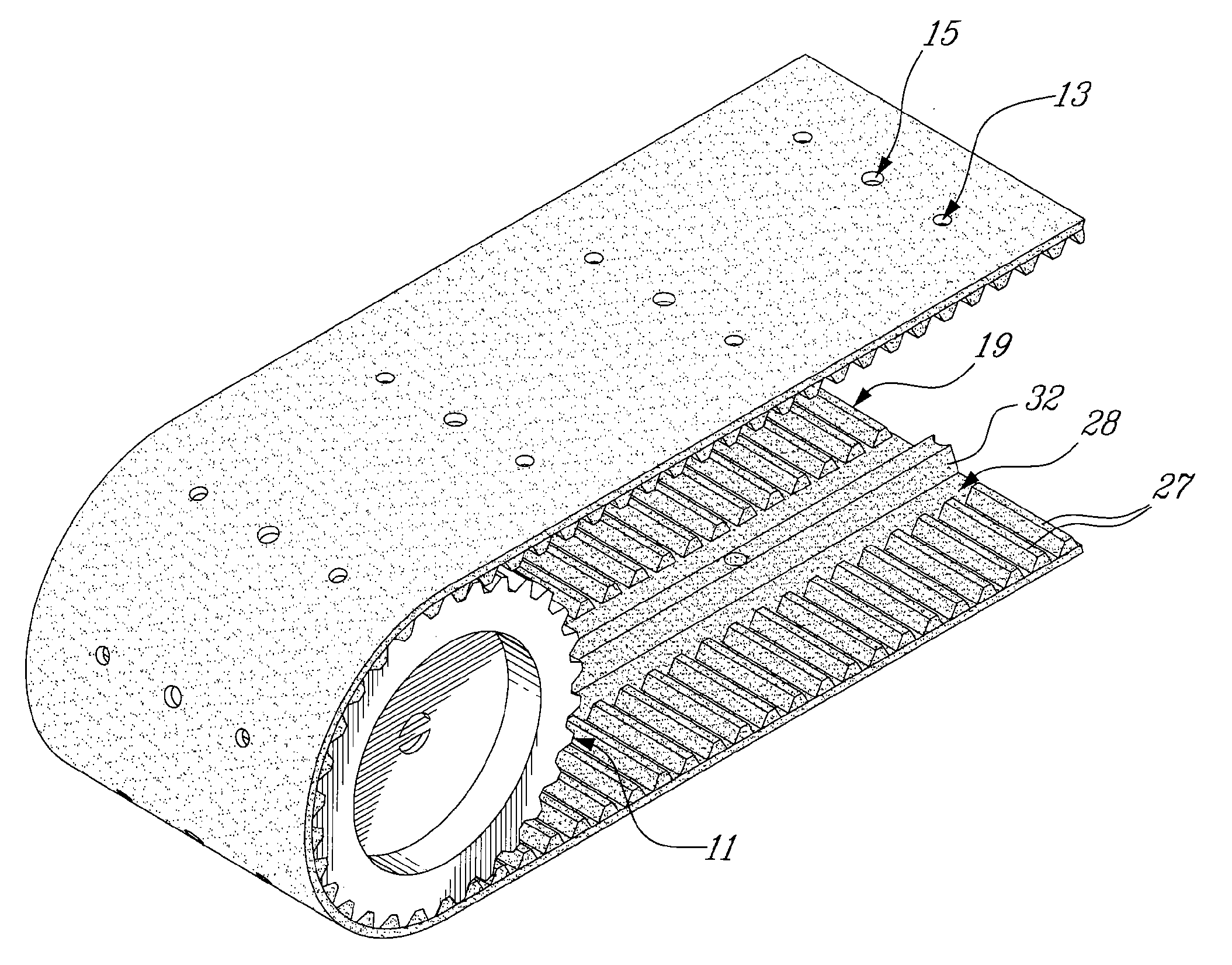
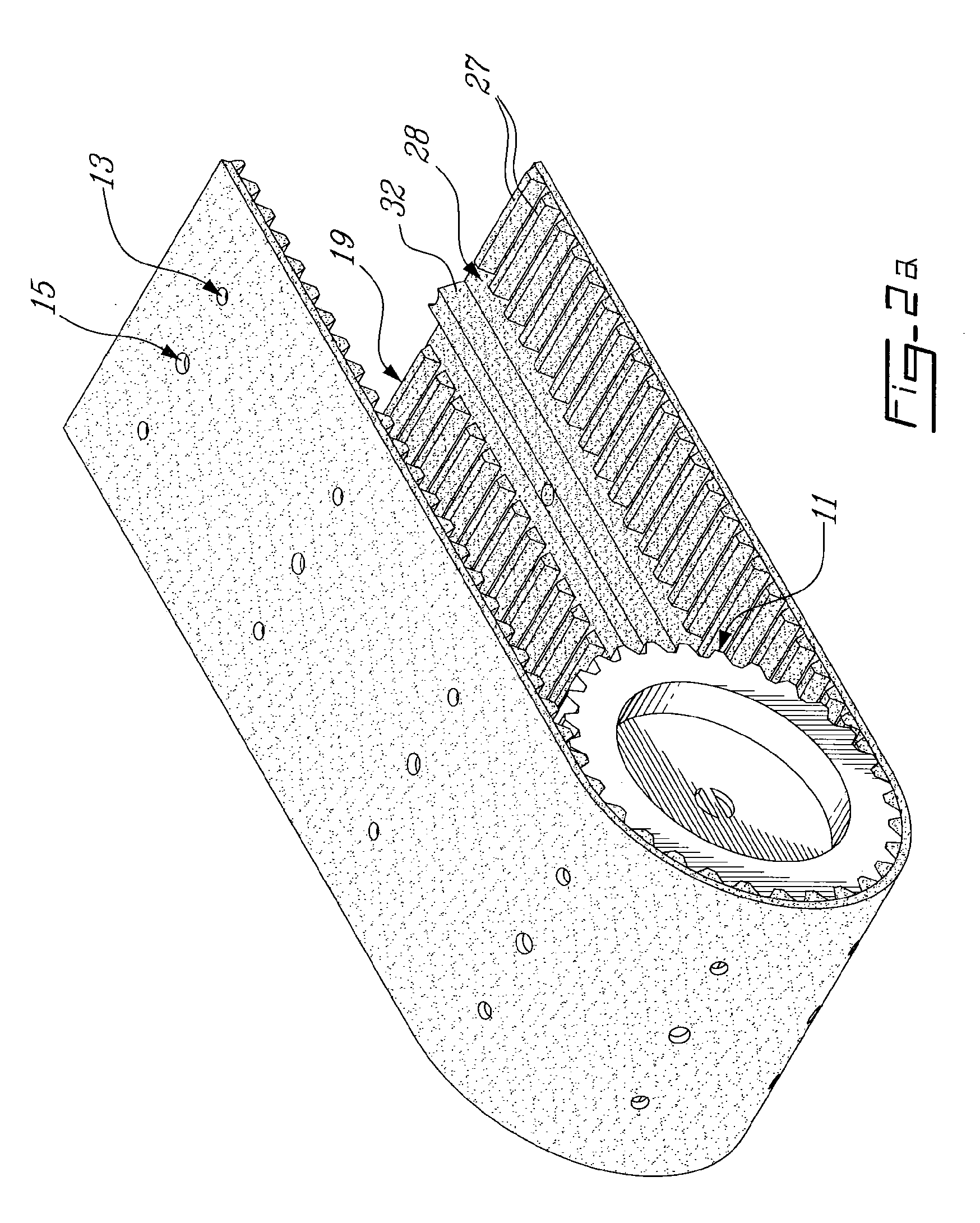
[0018]According to the present invention, the conveyor unit 16 located between the tenoner 10 and the conveyor unit 12 is a vacuum belt feeder. The vacuum belt feeder 16 generally comprises a suction zone (I), wherein the items 14 are retrieved from the tenoner 10, and a discharge zone (II) wherein the items 14 are released and placed on the conveyor unit ...


PUM


Abstract

A vacuum belt feeder comprising a means of conveyance having a pitch, for retrieving items from a supply zone, and then distributing them at target locations in a discharge zone.

Description

CROSS REFERENCE TO RELATED APPLICATIONS[0001]This application is a continuation-in-part of U.S. application Ser. No. 11 / 271,547 filed on Nov. 9, 2005, which itself claims priority on U.S. provisional application No. 60 / 626,872, filed on Nov. 12, 2004. All documents above are herein incorporated by reference.FIELD OF THE INVENTION[0002]The present invention relates to item transfer. More specifically, the present invention is concerned with a synchronized vacuum belt feeder.BACKGROUND OF THE INVENTION[0003]A number of manufacturing processes need, at some point thereof, transferring items from a supply zone to a discharge zone.[0004]In the food industry, vacuum belt feeders are used from ovens to containers for retrieving baked goods still in baking moulds and conveying them, while at some point along the way dropping the baked goods from the moulds. A means of suction actuated by vacuum is used on the vacuum belt feeders, which allows the moulds to adhere to the conveyor and then dr...

Claims


Application Information

Patent Timeline
IPC IPC(8): B65H29/24
CPCB65G21/2036B65H29/241B65H2404/23B65H2406/344B65H2406/361
Inventor LAPOINTE, ANDRE
Owner OSI MACHINERIE
Why Eureka
Try Eureka