
Air bag cushion

Inactive Publication Date: 2008-10-16
HYUNDAI MOBIS CO LTD
View PDF30 Cites 21 Cited by
  • Summary
  • Abstract
  • Description
  • Claims
  • Application Information

AI Technical Summary

Benefits of technology

[0017]The volume control panel may have a vent hole for discharging a gas introduced into the air bag cushion to control a pressure in the air bag cushion.
[0018]The upper chamber further comprises a volume control tether that is combined to the top panels interposing the volume control panel, such that the volume control panel's pressure which is made by gas inflated to the upper chambe

Problems solved by technology

However, such a structure has a drawback that work efficiency reduces because of a difficulty in controlling an optimal inner pressure and a difficulty in folding and arranging the air bag cushion in a vehicle.
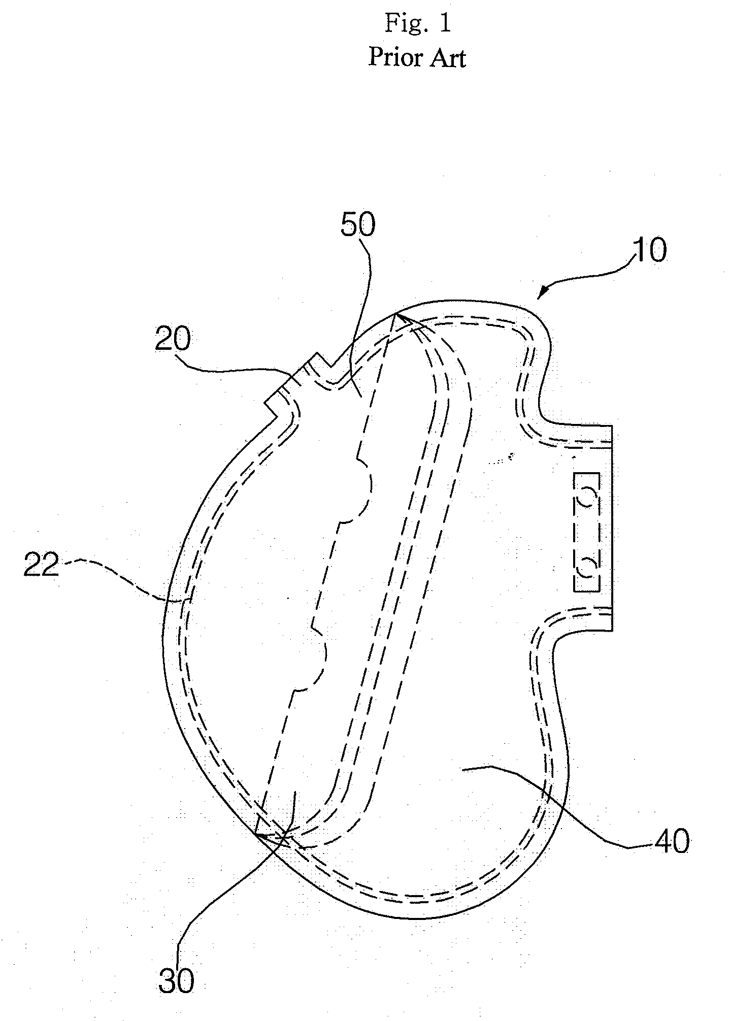
However, there is no choice but to provide the vent hole 20 at a side part of the upper chamber 50 because there is a difficulty in providing the vent hole 20 on the connection line 22.
First, when the vent hole 20 is provided on a panel directing to a side part of a vehicle, there is a drawback that when the air bag cushion 10 is inflated, the vent hole 20 is blocked since the side part of the vehicle is crushed.
Alternatively, when the vent hole 20 is provided at an opposite side part of the vehicle, there is a drawback that a gas is jetted directly to a passenger via the vent hole 20, causing a concern about a passenger's burn.

Method used


Image

  • Air bag cushion
  • Air bag cushion
  • Air bag cushion

Examples


Embodiment Construction

[0025]Preferred embodiments of the present invention will be described in a more detailed manner with reference to the drawings.

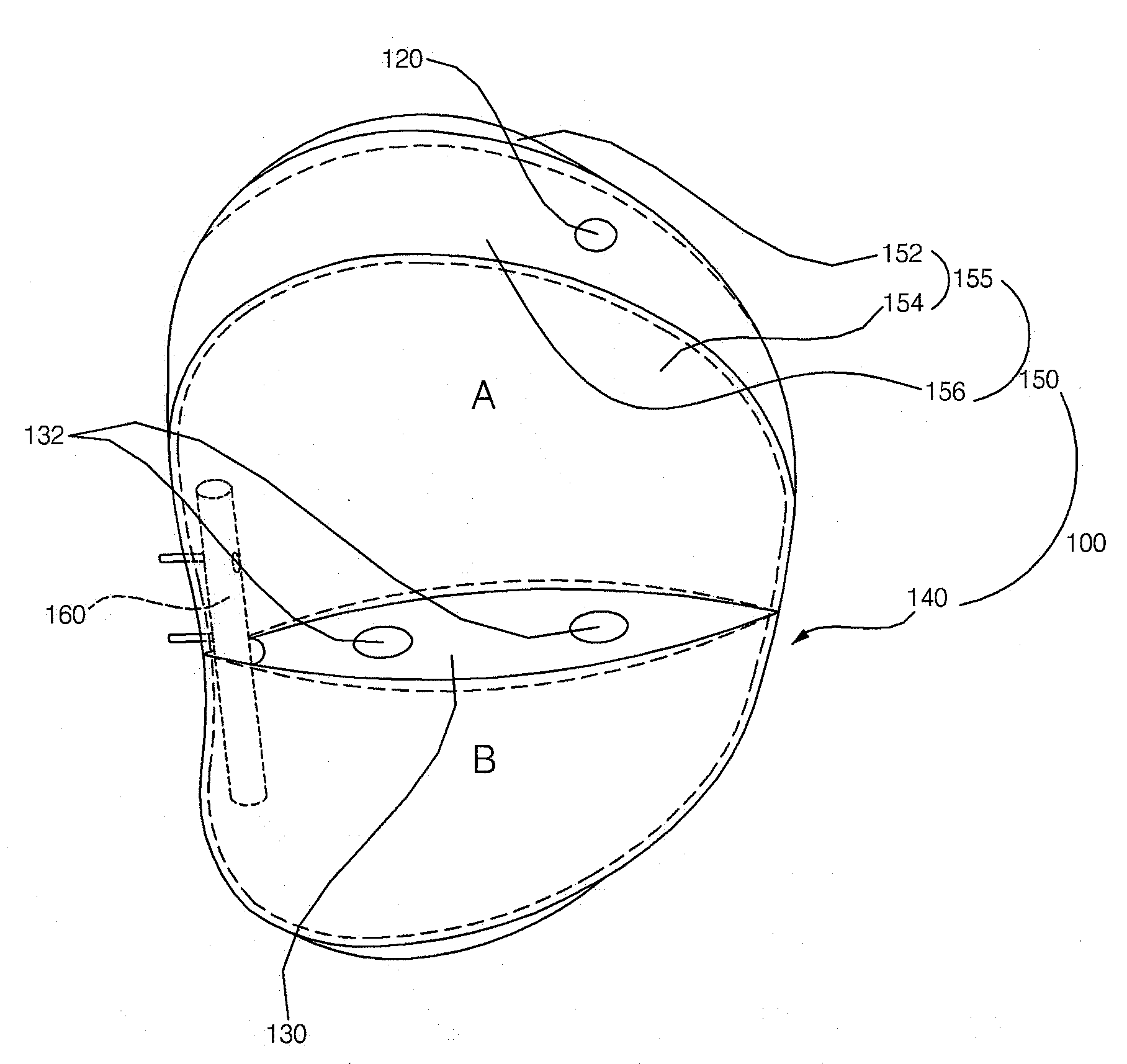
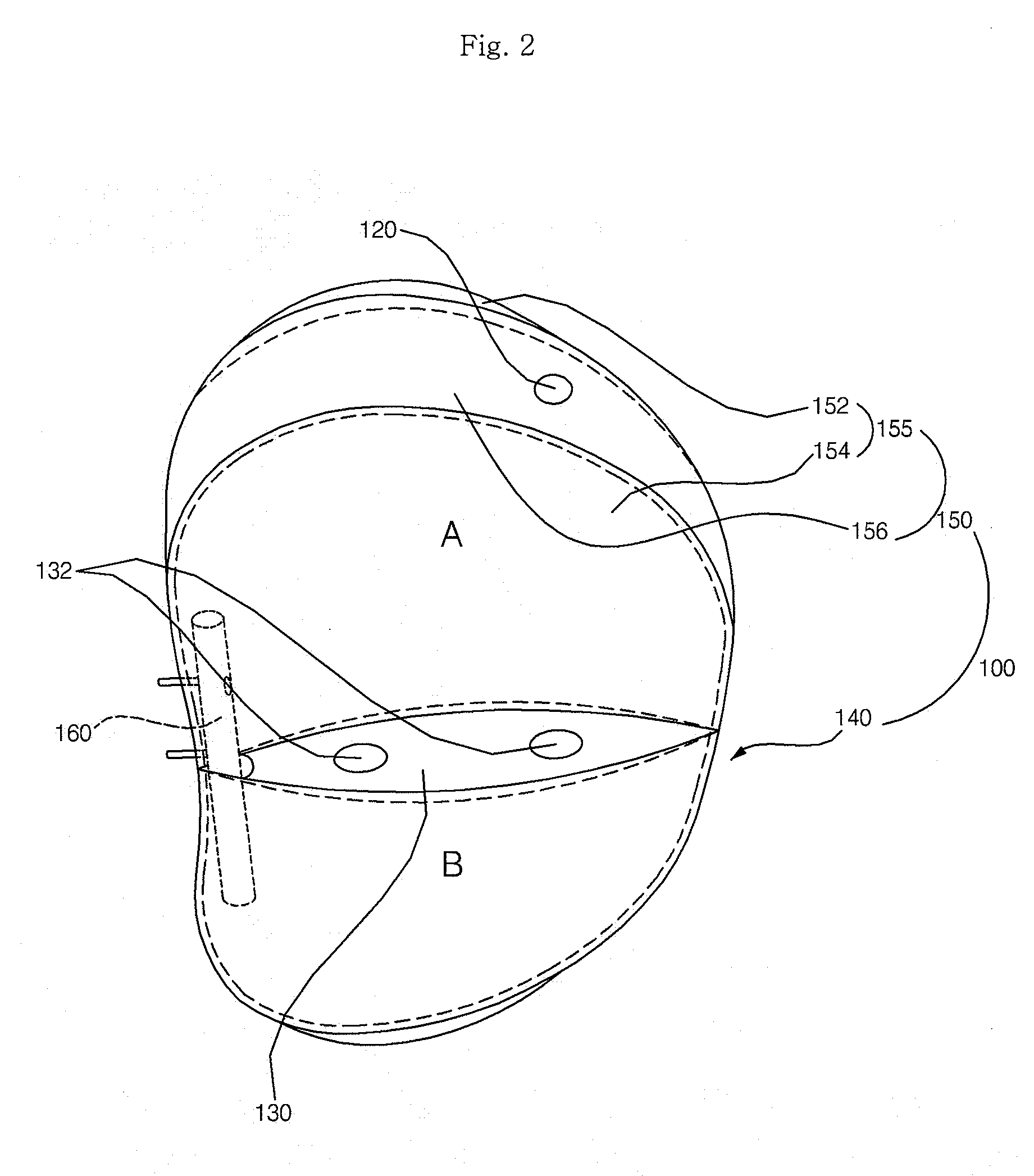
[0026]An air bag cushion 100 according to a first exemplary embodiment of the present invention will be described with reference to FIGS. 2 and 3 below.

[0027]The air bag cushion 100 includes an upper chamber 150 and a lower chamber 140, which are divided by a partition tether 130.

[0028]The lower chamber 140 can be configured in such a manner that two bottom panels 142 are sewn and connected with each other. The lower chamber 140 is not limited to a structure in which exactly two bottom panels 142 are connected with each other. It is enough that one or more bottom panels define a lower space (B).

[0029]The upper chamber 150 includes a plurality of top panels 155 partitioning an inner upper space (A), and a volume control panel 156 to be described later. The top panel 155 does not have to be configured with only two panels: a first side panel 152 and a second ...


PUM


Abstract

An air bag cushion includes a lower chamber including at least one bottom panel and defining a lower space by an introduced gas, and an upper chamber including a plurality of top panels and a volume control panel and combined with the lower chamber, the volume control panel being disposed in at least any one of spaces between the top panels and defining an upper space together with the top panels.

Description

[0001]This Nonprovisional application claims priority under 35 U.S.C. §119(a) on Patent Application No. 10-2007-0036936 filed in Korea on Apr. 16, 2007 and No. 10-2007-0084962 filed in Korea on Oct. 23, 2007, the entire contents of which are hereby incorporated by reference.BACKGROUND OF THE INVENTION[0002]1. Field of the Invention[0003]The present invention relates to an air bag cushion, and more particularly, to a side air bag cushion for more safely protecting a passenger from a physical impact occurring upon vehicle collision.[0004]2. Description of the Background Art[0005]Air bag systems are devices for absorbing, by elasticity of an air bag cushion, a physical impact occurring upon vehicle collision and protecting a passenger in a vehicle. Air bag systems can be classified into driver air bag systems, assistant driver air bag systems, and side air bag systems.[0006]In general, side air bag systems are installed in seats or car-body fillers. The side air bag systems protect pas...

Claims


Application Information

Patent Timeline
IPC IPC(8): B60R21/16
CPCB60R21/233B60R2021/23324
Inventor KIM, CHANG SOOJUN, JONG HYUB
Owner HYUNDAI MOBIS CO LTD
Learn More