Image forming apparatus and intermediate transfer unit

a technology of image forming apparatus and transfer unit, which is applied in the direction of electrographic process apparatus, instruments, optics, etc., can solve the problems of low productivity and inconvenient maintenance, and achieve the effect of improving productivity and ease of maintenance and facilitating the downsizing of the image forming apparatus

Active Publication Date: 2008-10-16
KYOCERA DOCUMENT SOLUTIONS INC
View PDF4 Cites 36 Cited by
  • Summary
  • Abstract
  • Description
  • Claims
  • Application Information

AI Technical Summary

Benefits of technology

[0008]An object of the present invention is to provide an intermediate transfer unit that facilitates down-sizing of an image forming apparatus and improves productivity and ease of maintenance of the image forming apparatus, and an image forming apparatus comprising the intermediate transfer unit.

Problems solved by technology

In a color image forming apparatus comprising a plurality of sets of toner containers and developing devices, the task of connecting these toner containers and developing devices respectively to each other through toner supply pipes becomes necessary when manufacturing and maintaining the apparatus, which results in low productivity and inconvenient maintenance.

Method used


Image

  • Image forming apparatus and intermediate transfer unit
  • Image forming apparatus and intermediate transfer unit
  • Image forming apparatus and intermediate transfer unit

Examples


first embodiment

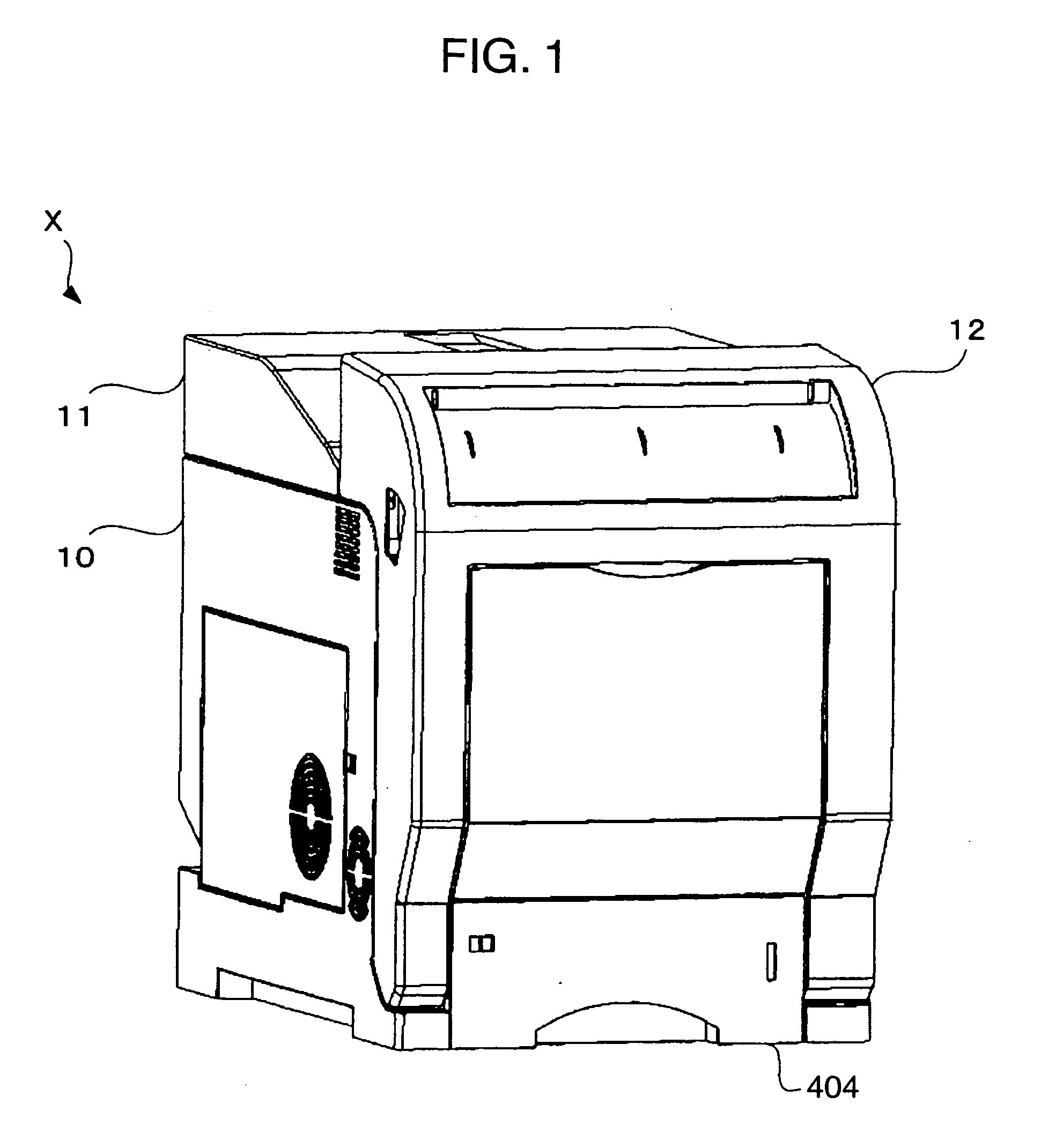
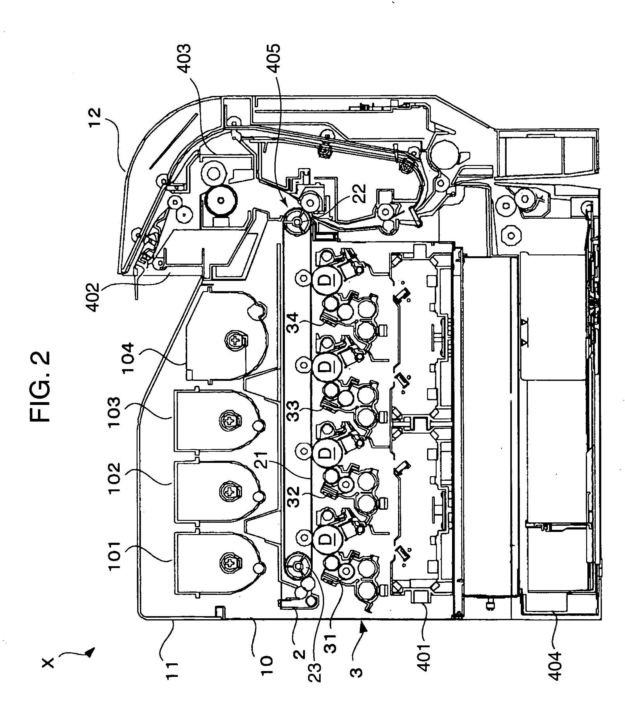
[0049]FIG. 1 is an external perspective view illustrating a color printer X according to a first embodiment of the image forming apparatus of the present invention. FIG. 2 is a side sectional view of the color printer of FIG. 1. Initially, the schematic constitution of a color printer X is explained below with reference to FIGS. 1 and 2. The color printer X is merely an example of an image forming apparatus of the present invention, and thus the present invention is applicable to a copying machine, a facsimile machine, a multifunction machine, and the like.

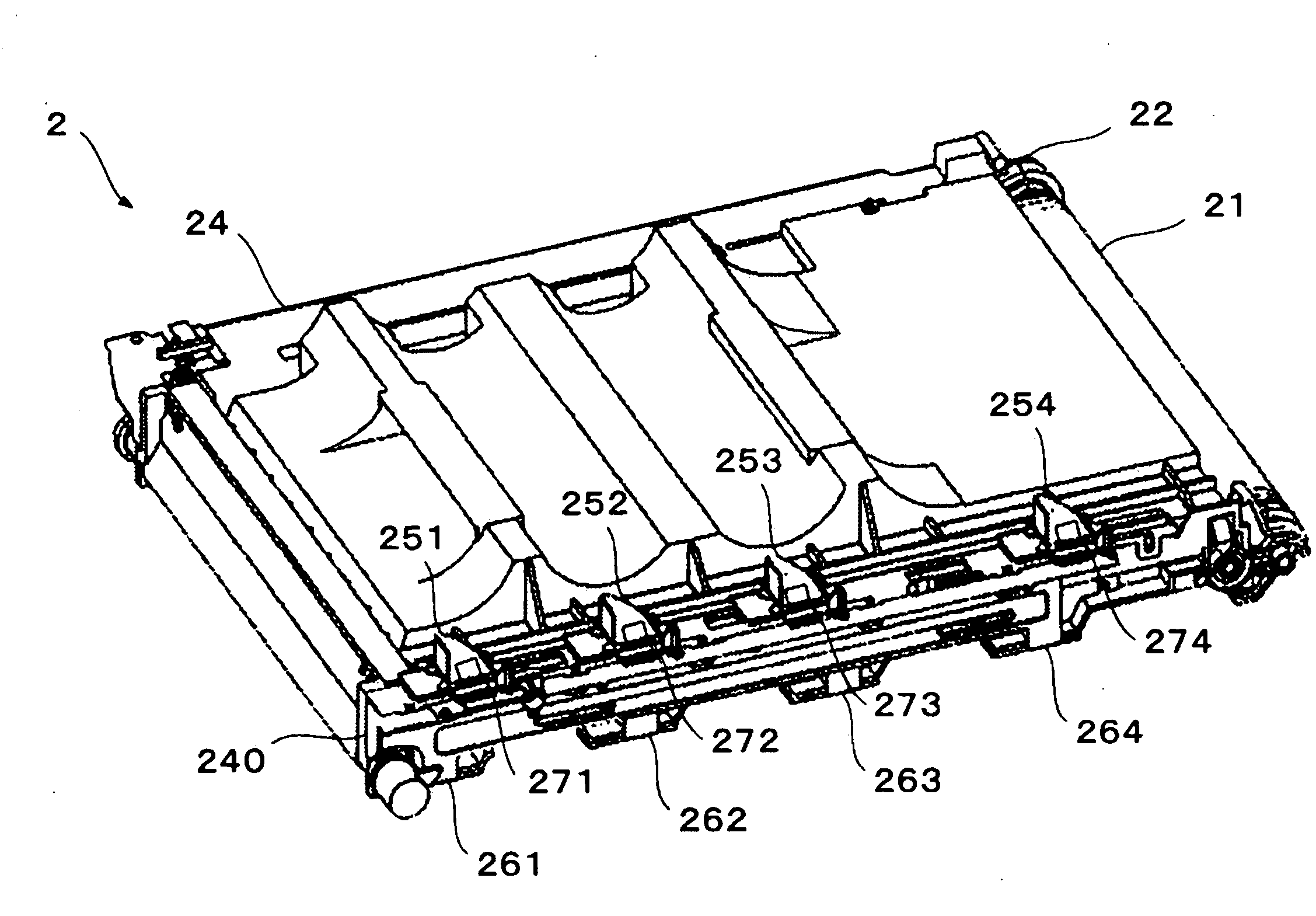
[0050]The color printer X has a schematic composition comprising toner containers 101, 102, 103, and 104 (developer containers), an intermediate transfer unit 2, an image forming unit 3 comprising developing devices 31, 32, 33, and 34, a laser scanner unit 401, a paper discharge unit 402, a fixing unit 403, a paper feed cassette 404, a housing 10 of an apparatus main body, a top cover 11, and a front cover 12. The color printer X ...

second embodiment

[0101]A second embodiment includes a modification of the toner conveying member 290 according to the above described first embodiment, but the other structures are identical to that of the first embodiment.

[0102]The toner conveying member 290 as described in the first embodiment provides the first, the second, and the third screw sections 291, 292, and 293 that convey the toner only in the horizontal direction within the toner supply paths 241, 243, and 244. For example, in FIG. 11, the first screw section 291 conveys the toner only in a left direction, while the second screw section 292 conveys the toner particles only in a right direction.

[0103]FIG. 16 is a cross sectional view of the intermediate transfer unit 2A according to the second embodiment in which a toner conveying member 2900 which is a modification of the toner conveying member 290 is described. FIG. 17 is a partially enlarged view of an area B encircled by an alternating long and short dashed line in FIG. 16. Like ref...

third embodiment

[0106]A third embodiment has such a structure that the developing devices can be precisely positioned with regard to the intermediate transfer unit, and has a basic structure identical to the above described first embodiment.

[0107]In the above exemplified color printer X, it is desirable that each apparatus unit is readily detachable for the purpose of assembly and maintenance thereof. However, a mounting position of the developing device 3 with regard to the intermediate transfer unit 2 should be accurate and the positional accuracy and convenience of an attachment / detachment operation should be satisfied at the same time.

[0108]FIGS. 18 and 19 are perspective views illustrating the intermediate transfer unit 2B according to the third embodiment mounted on a frame of the apparatus main body of the color printer X. FIGS. 18 and 19 exemplify a first main body frame 41 positioned at a side surface of a side where the toner supply path 240 of the intermediate transfer unit 2B is provide...


PUM


Abstract

An intermediate transfer unit of an image forming apparatus is provided between a plurality of developer containers for containing developer and a plurality of developing devices. The intermediate transfer unit includes an intermediate transfer unit for secondarily transferring primarily transferred developed images from the plurality of image carriers onto a paper, an intermediate transfer unit driving mechanism for driving the intermediate transfer unit, and a housing for supporting the intermediate transfer unit driving mechanism. One end of the housing includes a plurality of developer inlet ports positionally corresponding to the developer supply ports of the developer containers respectively, a plurality of developer outlet ports positionally corresponding to the developer receiving ports of the developing devices respectively, and a plurality of developer supply paths connecting between the developer inlet ports and the developer outlet ports respectively.

Description

BACKGROUND OF THE INVENTION[0001]1. Field of the Invention[0002]The present invention relates to an intermediate transfer unit for the secondary transfer onto sheet of developed images that were primarily transferred onto a plurality of image carriers, and an image forming apparatus comprising the intermediate transfer unit.[0003]2. Description of the Related Art[0004]In a conventional image forming apparatus having an intermediate transfer unit between a toner container for containing developer (toner) and a developing device, a toner supply pipe for supplying toner from the toner container to the developing device is provided such that the pipe detours around a housing of the intermediate transfer unit. Such an arrangement is disclosed in, for example, FIG. 7 of Japanese Unexamined Patent Publication No. 2004-139031.[0005]FIG. 40 of this specification is a citation of FIG. 7 from the above patent document. As shown in FIG. 40, a setting space S between a toner container 32Y and a ...

Claims


Application Information

Patent Timeline
Patent Type & Authority Applications(United States)
IPC IPC(8): G03G15/04G03G15/08
CPCG03G15/161G03G15/1605G03G15/0875G03G15/0855G03G15/0886G03G15/0865G03G15/0879
Inventor FURUTA, SHINJIYAMAMOTO, KOJUFUJII, HIROKAZUMORISHITA, HIROKIIKEBATA, YOSHIAKI
Owner KYOCERA DOCUMENT SOLUTIONS INC
Why Eureka
Try Eureka