Aperture apparatus

a technology of aperture apparatus and drive ring, which is applied in the field of aperture apparatus, can solve the problems of large size and complex structure of aperture apparatus having drive ring, and achieve the effect of simple structur

Inactive Publication Date: 2008-03-04
SEIKO PRECISION CO LTD
View PDF13 Cites 7 Cited by
  • Summary
  • Abstract
  • Description
  • Claims
  • Application Information

AI Technical Summary

Benefits of technology

[0008]It is therefore an object of the present invention to address the above-described circumstances and provide an aperture apparatus having a simpler structure that can swing small aperture sectors in an efficient manner.
[0010]According to the present invention, when the first small aperture sector shields the lens opening by means of the cam openings respectively provided in the first small aperture sector and the second small aperture sector, the second small aperture sector is retained in the receding position. In a similar manner, when the second small aperture sector shields the lens opening by means of the cam openings respectively provided in the first small aperture sector and the second small aperture sector, the first small aperture sector is retained in the receding position. It is therefore possible to form different aperture states with certainty by swinging the first small aperture sector and the second small aperture sector without using a return spring. In addition, one of the first small aperture sector and the second small aperture sector can be retained in the receding position, thereby eliminating the necessity of a stop position deciding member. This can promote downsizing.

Problems solved by technology

The aperture apparatus having the drive ring generally has a complex structure, and tends to be large in size.

Method used


Image

  • Aperture apparatus
  • Aperture apparatus
  • Aperture apparatus

Examples


first embodiment

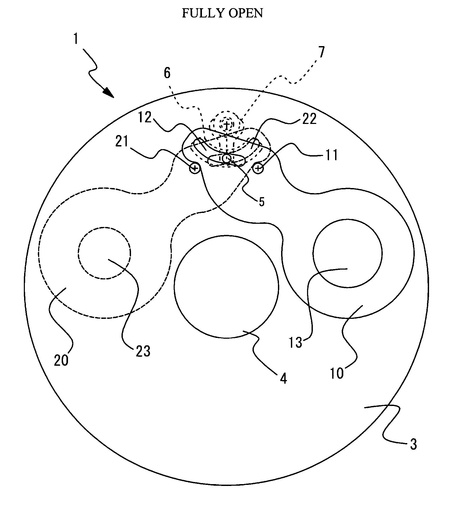
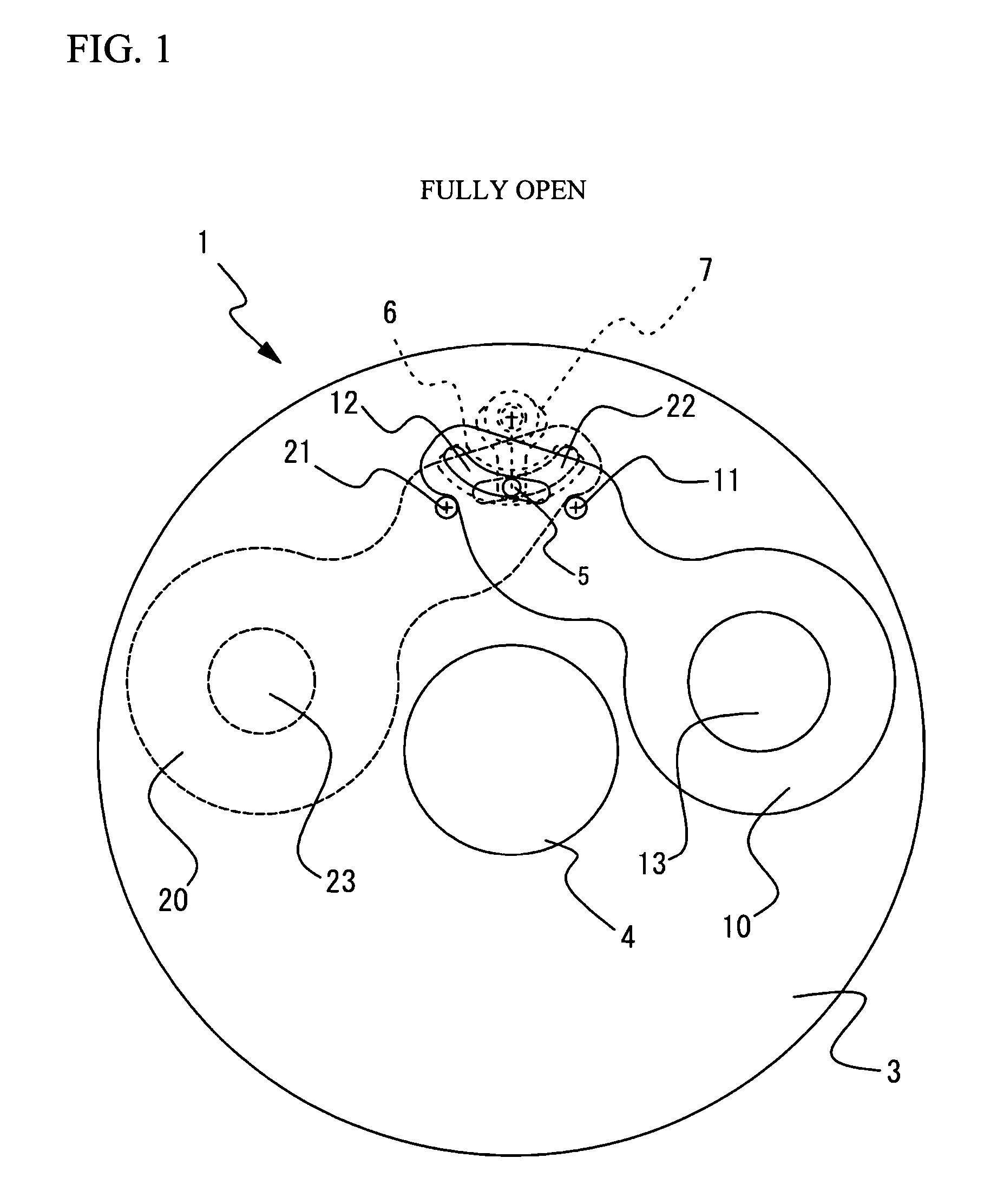
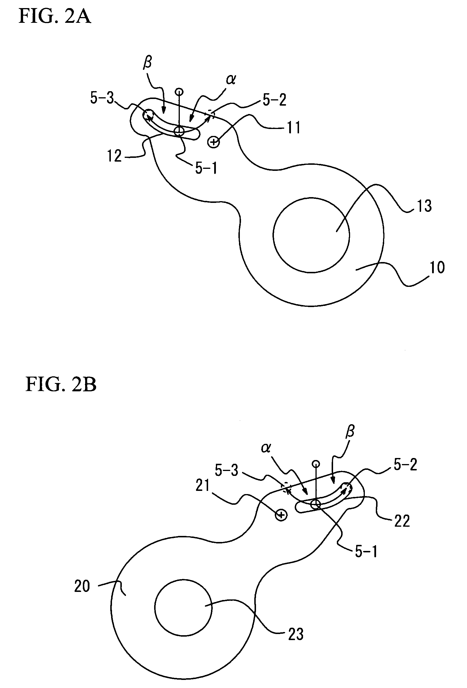
[0023]FIG. 1 is a view illustrating an aperture apparatus 1 in a fully open state in accordance with the present invention. FIG. 2A and FIG. 2B are views illustrating two small aperture sectors (small aperture blades) included in the aperture apparatus 1 shown in FIG. 1. In addition, FIG. 3 is a view illustrating the aperture apparatus 1 in a first-step aperture state. FIG. 4 is a view illustrating the aperture apparatus 1 in a second-step aperture state. Further, FIG. 5 is a side view showing a positional relationship between a substrate and an actuator included in the aperture apparatus 1 shown in FIG. 1.

[0024]Referring to FIG. 1, the aperture apparatus 1 is provided with a shutter substrate 3 and two small aperture sectors. A first sector 10 is a first small aperture blade having a relatively large-sized small aperture opening 13 (first small aperture opening). A second sector 20 is a second small aperture blade having an aperture opening 23 (second small aperture opening), which...

second embodiment

[0041]FIG. 6 is a view illustrating the fully open state of the aperture apparatus 50 in accordance with the present invention. FIG. 7A through FIG. 7D are views illustrating two small aperture sectors (small aperture blades) and two complementary sectors that complement the shielding thereof. In addition, FIG. 8 is a view illustrating the aperture apparatus 50 in the first-step aperture state. FIG. 9 is a view illustrating the aperture apparatus 50 in the second-step aperture state. Hereinafter, in the aperture apparatus 50, the same components as those in the aperture apparatus 1 have the same reference numerals.

[0042]The aperture apparatus 50 includes originally provided two small aperture sectors 60 and 70 on the right-hand side and on the left-hand side of the lens opening 4. The first sector 60 is the first small aperture blade having a relatively large-sized small aperture opening 63. The second sector 70 is a second small aperture blade having a small aperture opening 73, wh...


PUM


Abstract

An aperture apparatus includes a substrate having a lens opening, a first aperture sector having a first aperture opening, a second aperture sector having a second aperture opening, and a drive pin that is engaged in cam openings respectively formed in the first aperture sector and in the second aperture sector and that swings the first aperture sector and the second aperture sector. The first aperture sector and the second aperture sector are located in receding positions from the lens opening, when the drive pin is in an initial position. The cam openings include a swing region and a non-swing region, the swing region guiding a corresponding sector to the lens opening as the drive pin moves from the initial position, the non-swing region retaining the other sector in the receding position, when one of the first aperture sector and the second aperture sector is guided to the lens opening.

Description

CROSS-REFERENCE TO RELATED APPLICATIONS[0001]This application is a continuation of and claims priority to International Patent Application No. PCT / JP2004 / 017474 filed on Nov. 25, 2004, which claims priority to Japanese Patent Application No. 2003-414950 filed on Dec. 12, 2003, subject matter of these patent documents is incorporated by reference herein in its entirety.BACKGROUND OF THE INVENTION[0002]1. Field of the Invention[0003]This invention generally relates to aperture apparatuses for use in optical apparatuses, and more particularly, to an aperture apparatus suitable for use in an optical apparatus such as a digital camera, camcorder, or the like.[0004]2. Description of the Related Art[0005]Conventionally, there have been proposed aperture apparatuses mounted on cameras. It is well known that an aperture apparatus includes multiple aperture blades driven by a drive ring to realize a multi-step aperture mechanism of five or more steps. It is also well known that an aperture ap...

Claims


Application Information

Patent Timeline
Patent Type & Authority Patents(United States)
IPC IPC(8): G03B9/02G03B9/07
CPCG03B9/02
Inventor NUMNUAL, PHICHETKAWAMOTO, HISASHIOISHI, SEIICHITAKANO, OSAMU
Owner SEIKO PRECISION CO LTD
Why Eureka
Try Eureka