
Shifting register and driving method thereof as well as gate driving circuit

A technology of shift register and potential, which is applied in the field of gate drive circuit, shift register and its drive, can solve the problems of unfavorable narrow frame and large space occupied by gate drive circuit, and achieve the effect of reducing the number

Inactive Publication Date: 2017-09-26
BOE TECH GRP CO LTD
View PDF6 Cites 7 Cited by
  • Summary
  • Abstract
  • Description
  • Claims
  • Application Information

AI Technical Summary

Problems solved by technology

[0003] However, each stage of the shift register in the existing gate drive circuit can only be used to drive one row of gate lines, so the entire gate drive circuit occupies a large space, which is not conducive to the realization of narrow borders

Method used


Image

  • Shifting register and driving method thereof as well as gate driving circuit
  • Shifting register and driving method thereof as well as gate driving circuit
  • Shifting register and driving method thereof as well as gate driving circuit

Examples


Embodiment 2

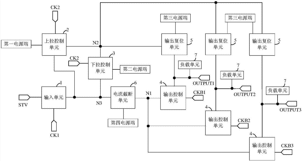
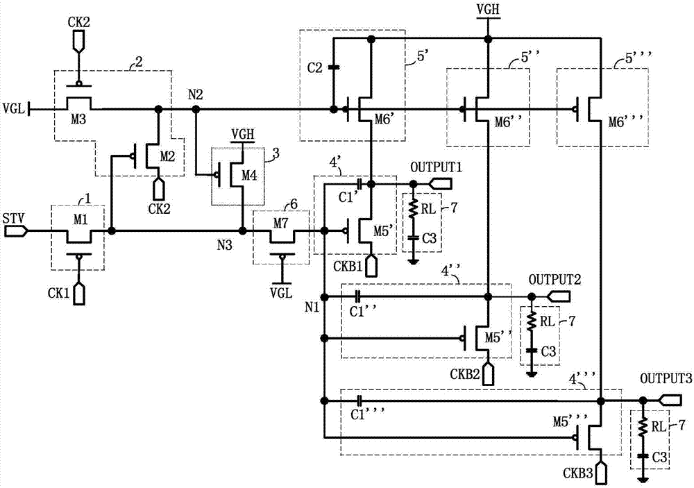
[0063] figure 2 The circuit schematic diagram of the shift register provided for the second embodiment of the present invention, such as figure 2 as shown, figure 2 The circuit schematic shown is figure 1 The embodiment of the structural diagram shown in this embodiment is described by taking the output control unit 4' / 4" / 4"' and the output reset unit 5' / 5" / 5"' as an example. .

[0064] Optionally, the input unit 1 includes: a first transistor M1; the control electrode of the first transistor M1 is connected to the first clock signal line CK1, the first electrode of the first transistor M1 is connected to the input signal terminal STV, and the first transistor M1 The second pole is connected to the first node N1.

[0065] The pull-up control unit 2 includes: a second transistor M2 and a third transistor M3; the control pole of the second transistor M2 is connected to the first node N1, the first pole of the second transistor M2 is connected to the second clock signal li...


PUM


Abstract

The invention discloses a shifting register and a driving method thereof, as well as a gate driving circuit. The shifting register comprises an input unit, an upper control unit, a lower control unit, a plurality of output control units and output reset units, wherein each output control unit is connected with a corresponding wire of a clock signal to be output and a signal output end and used for inputting the clock signal which is provided by the wire of the clock signal to be output and is to be output to the corresponding signal output end under the control of the electric potential of a first node; each output reset unit is used for inputting third voltage provided by a third power supply end to the signal output end under the control of the electric potential of a second node. According to the shifting register, the plurality of output control units are provided and can be used for driving a plurality of gate lines, so that the quantity of the shifting registers in a gate electrode driving circuit can be effectively decreased, and the gate electrode driving circuit can be of a small size, and as a result, a narrow side frame of a panel can be displayed.

Description

technical field [0001] The invention relates to the field of display technology, in particular to a shift register, a driving method thereof, and a gate driving circuit. Background technique [0002] The basic principle of TFT-LCD (Thin Film Transistor-Liquid Crystal Display, thin film transistor liquid crystal display device) to realize a frame display is to input a square wave of a certain width to each row of pixels sequentially from top to bottom through the gate (Gate) drive. Strobe, and then drive the signal required for each row of pixels through the source (Source) and output from top to bottom in turn. [0003] However, each stage of the shift register in the existing gate driving circuit can only be used to drive one row of gate lines, so the entire gate driving circuit occupies a large space, which is not conducive to the realization of narrow borders. [0004] It can be seen that how to effectively reduce the occupied space of the gate driving circuit is a techn...

Claims


Application Information

Patent Timeline
Patent Type & Authority Applications(China)
IPC IPC(8): G09G3/36G11C19/28
CPCG09G3/3677G11C19/28G09G2310/0286
Inventor 郑灿
Owner BOE TECH GRP CO LTD
Learn More