Heat exchanger unit

a heat exchanger and semiconductor technology, applied in the direction of semiconductor devices, lighting and heating apparatus, basic electric elements, etc., can solve the problems of increasing the thermal resistance, reducing so as to improve optimize the heat conduction effect. , the effect of small surface tension

Inactive Publication Date: 2010-01-21
NEC CORP
View PDF7 Cites 7 Cited by
  • Summary
  • Abstract
  • Description
  • Claims
  • Application Information

AI Technical Summary

Benefits of technology

[0024]It may not always be necessary that the actual micro-structure is completely identical to that illustrated in FIG. 2, wherein a state of allowing stable residence of bubbles by virtue of the double-inlet structure, and uniform provision of the structure over the entire heat conduction surface may contribute to improvement and optimization of the heat conduction effect, based on boiling as a macroscopic consequence. The vapor bubbles of a refrigerant having a small surface tension may further downsize themselves in the process of dissociation, so that micronization of the recess structure to as small as several micrometers or around may be effective in view of promoting the downsizing. As a consequence, the boiling may be expected to start at a temperature more closer to the boiling point.

Problems solved by technology

As explained in Non-Patent Document 1, any conventional efforts for assimilating such ideal geometry have resulted in thickening over the entire surface geometry (100 μm to 1 mm or thicker), and any efforts have failed in obtaining the ideal geometry of the recesses.
The thickness and the recesses of several hundred micrometers to 1 mm or around may result in higher thermal resistance as compared with smaller structures, and may raise a problem in retention property of the vapor nuclei, when a refrigerant having a surface tension smaller than that of water is used.
Furthermore, while the geometry shown in Non-Patent Document 1 is not given with a scale, the size and so forth of the opening in an actual structure may vary, so that it may be very easy to presume that this raises negative effects, depending on physical properties of the refrigerant.
Although various micro-structures have been experimented, no invention has been successful to provide a surface geometry obtained by optimizing an ideal double-inlet structure with respect to an actual refrigerant.
Various trails have been made on the surface conditions, only to fail in achieving the ideal geometry, because thermal resistance may increase as the thickness of the surface increases.
Most of the surfaces at present are not structurally idealized, and is therefore far from being optimized for the nuclei, with some exceptions exhibiting the effect of heat conduction by virtue of the micro-structure.
It may therefore be understood from the above that the radius of curvature of the gas-liquid interface is determined by the angle of contact point of three phases, that are gas, liquid and solid phases (reference numerals 20 and 21 in FIG. 9 and FIG. 10, representing the angles on the liquid side), and that use of the V-shape structure for a refrigerant having a small surface tension may result in only a poor effect of retention of vapor nuclei.

Method used


Image

  • Heat exchanger unit
  • Heat exchanger unit
  • Heat exchanger unit

Examples


example 1

[0046]As illustrated in FIG. 5, a heat exchanger unit given with a flow path 12 for refrigerant, formed so as to allow the refrigerant to pass over a flat plate 7 provided with a surface-modified portion, is manufactured. The heat exchanger unit has a heating element 6, and a heat exchanger block 10 provided over the heating element 6. The heat exchanger block 10 has a heat exchanger upper holder 11 and a modified surface 7. The heat exchanger upper holder 11 is provided with an inlet 8 and an outlet 9, allowing therethrough introduction and discharge of a liquid refrigerant, respectively. Inside the heat exchanger block 10, there is provided the flow path 12 allowing therethrough circulation of a liquid refrigerant. Since the flow path 12 is provided so as to allow the refrigerant to pass over the modified surface 7, the flow rate of the refrigerant may be varied, making it possible to avoid adverse effects such as dry-out ascribable to generation of a large amount of bubbles.

example 2

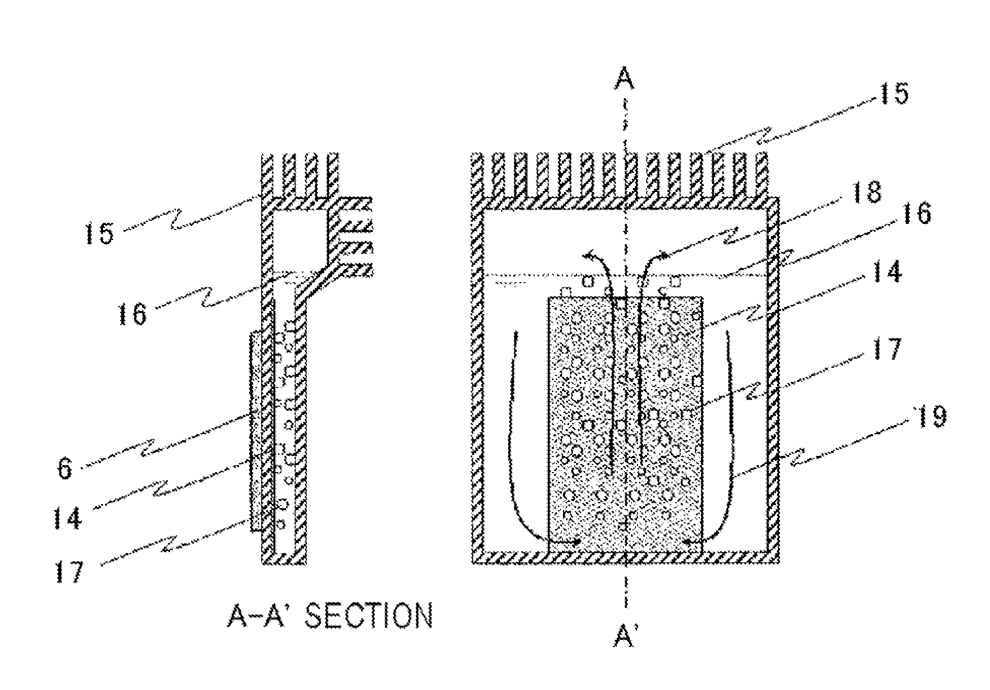
[0047]The heat conduction surface provided with the surface-modified portion may be used under pool boiling, while needing a mode capable of avoiding the dry-out. One possible method may be such as selectively providing a surface-modified portion 14, rather than providing it over the entire surface of the heat conduction surface 13. For example, as illustrated in FIG. 6, the surface-modified portion 14 may possibly be provided only at around the center of the heat conduction surface 13, so as to induce natural convection.

[0048]The number of convection cells on the flat plate is an issue of the Rayleigh-Benard Convection problem, and is determined by a function of the depth of refrigerant and the area of the bottom surface. In this Example, by selectively providing surface-modified portion 14 while making use of the convection cells, the boiling bubbles may effectively be taken apart from the heat conduction surface soon after dissociation, and thereby the liquid may be supplied to t...

example 3

[0049]The surface-modified portion of the present invention may be adoptable also to a heat conduction portion having a form generally called micro-channel, among forced-convection boiling refrigerant type cooling units, aimed at achieving a heat conduction effect by forming fine flow paths (FIG. 7). The micro-channel limits the width of the flow path to as small as the size of the boiling bubbles or below, in order to extremely expand the contact area between the heat conduction surface and a refrigerant. As a consequence, the bubbles may stagnate and the flow may accordingly be unbalanced among the flow paths, depending on refrigerant and conditions of flow.

[0050]By providing the surface modification of the present invention, the boiling bubbles may be allowed to generate uniformly in the flow paths, and may therefore be reduced in size when they dissociate from the heat conduction surface. Since small bubbles are unlikely to stagnate, so that the flow may more readily be balanced...


PUM


Abstract

According to the present invention, there is provided a heat exchanger unit having, over a base, a surface-modified portion composed of a metal, the surface-modified portion being brought into contact with a flow path provided for a liquid refrigerant, wherein the liquid refrigerant is a liquid having a surface tension smaller than that of water, and the surface-modified portion has a porous structure, in which a plurality of recesses are provided on the flow path side thereof, each recess has an introduction path having a cross-section area gradually reduced from the inlet of the recess, and a cavity communicated with the introduction path while placing an inflection portion in between, and the shortest distance between the inflection portion and the flow path is larger than the shortest distance between the cavity and the flow path.

Description

TECHNICAL FIELD[0001]The present invention relates to a semiconductor heat exchanger unit, and in particular to a semiconductor heat exchanger unit making use of phenomenon of boiling.BACKGROUND ART[0002]For the purpose of conducting a large energy of heat generated by semiconductor devices, there has been developed a method of obtaining a high level of cooling effect based on latent heat of vaporization of a refrigerant capable of boiling at a temperature not higher than the upper limit temperature of operation of the semiconductor devices. In recent years, investigations have been focused on influences of surface conditions of a boiling surface and thermo-physical properties of refrigerant, which govern the size and density of generated vapor bubbles, aiming at stabilizing and optimizing the heat conduction effect obtainable by boiling of the refrigerant.[0003]It has been known that the heat conduction characteristics may be improved in pool boiling on a flat plate, by forming an ...

Claims


Application Information

Patent Timeline
Patent Type & Authority Applications(United States)
IPC IPC(8): F28F13/02F28D15/02F28F7/00
CPCF28D15/046F28F13/18H01L23/427H01L2924/3011H01L2924/0002H01L2924/00
Inventor SAKAMOTO, HITOSHIMIKUBO, KAZUYUKIKITAJO, SAKAE
Owner NEC CORP
Why Eureka
Try Eureka